Chapter 2 XAG Agricultural Drone System Module and Working Principle
Connection between flight control and each system module
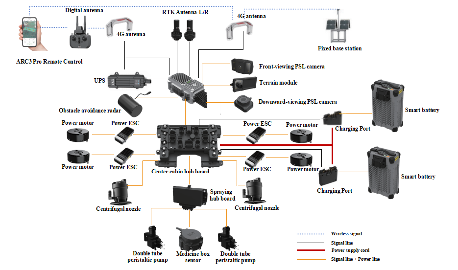
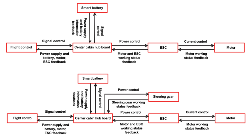
P100 Pro Agricultural Drone system module connection diagram
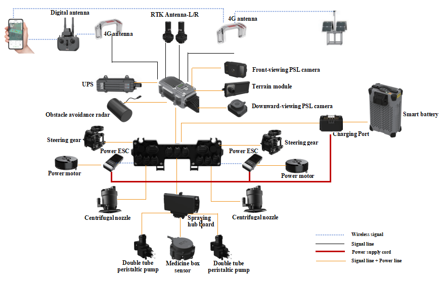
V50 Pro Agricultural Drone system module connection diagram
Powertrain
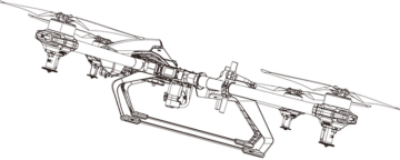
The Powertrain of P100 Pro agricultural drone is mainly composed of center cabin hub board, power electric regulator, power motor and propeller. It provides power output for the whole machine. Among them, the center cabin hub board is responsible for distributing the flight control signal and battery current to the electric regulator. Electric control is responsible for controlling the current of the motor according to the flight control signal, controlling the speed of the motor, and the motor is responsible for driving the propeller to rotate. The propeller generates lift, allowing the drone to fly.
Powertrain module connection
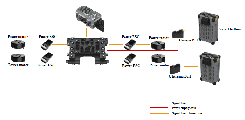
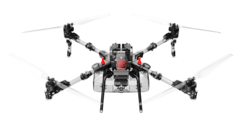
P100 Pro Agricultural Drone Powertrain
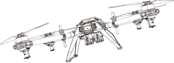
V50 Pro Agricultural Drone Powertrain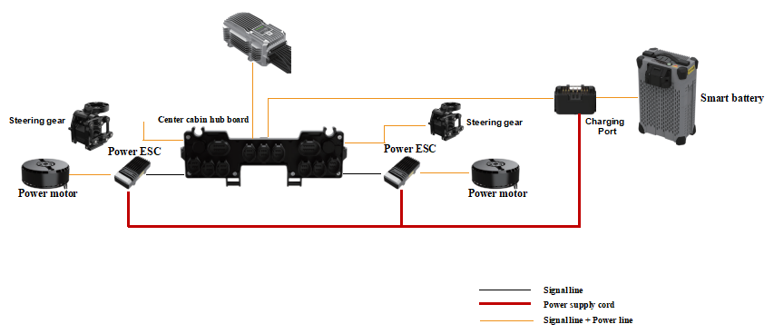
Powertrain data flow analysis
Powertrain signal transmission flow
The control of the Powertrain of the XAG 2023 agricultural drone is mainly realized through two links, one is the power output link, which distributes power to the motors, and drive the propellers to allow the drone to fly. The other is the signal transmission link, which enables the flight control to obtain the status information of the electric regulation. At the same time, it can send control information to the electric regulator, and the electric regulator adjusts the speed of the motor, so as to change the flight attitude of the drone.
• Power supply output link: Battery is the power source for the drone flight. Firstly, the battery supplies power to the power distribution board through the battery tail plug. The power line collection board distributes the current to each electric regulator, and at the same time, the center cabin hub board supplies power to the flight control through the connecting line of the PTS socket. After that, the electric regulator transmits the current to the motor to drive the motor to rotate.
• Signal transmission link: the flight control transmits the control signal to the center cabin hub board through the connecting line of the PTS socket. The center cabin hub board distributes the power signal to each corresponding ESC (Electronic Speed Controller). The ESC controls the rotating speed of the motor by controlling the current output. Flight control is also the brain of the drone, and the brain needs to obtain the relevant parameters of the Powertrain in real time. Information such as current, motor speed, ESC power and temperature is fed back to the flight control through the connecting line of the PTS socket.
Power module introduction
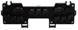
Center cabin hub board
It is mainly used to supply power to flight control and execution systems. And can distribute the flight control to the control signal of the electric control and collect the feedback information of the electric control to the flight control.
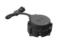
Electronic Speed Controller(ESC)
FOC ESC is field-oriented control, also known as vector control, which is a technology that uses frequency converter to control three-phase AC motor. The motor output power is controlled by adjusting the output frequency of the frequency converter, the magnitude and angle of the output voltage.
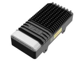
Agricultural drone FOC ESC
Power Motor
The 2023 XAG agricultural drone uses brushless DC motor (BLDCM), which uses semiconductor switching devices to realize electronic commutation. That is to say, the traditional contact commutator and brush are replaced by electronic switching devices.
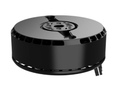
Agricultural drone power motor
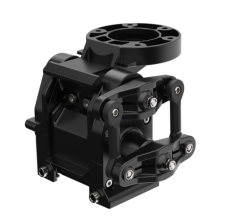
Steering Gear
V50 Pro agricultural drone adopts two-stage planetary gear reduction and impact-proof connecting rod design, which drives the connecting rod through gear rotation.The connecting rod pulls the motor to tilt to change the angle of the propeller plane.
Propeller
The 2023 XAG Agricultural Drone Propeller
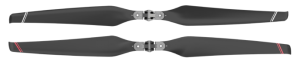
55-inch high-efficiency propeller
Introduction to Powertrain Test Interface
P-Series Powertrain Test Interface
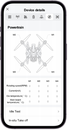
- Rotating speed: indicates the operating speed of the motor, and the unit is rev/min.
- Current: indicates the output current of the ESC, which varies with the load.
- Die temperature: indicates the die temperatures.
- Main board temperature: indicates the temperature of ESC MOS tub.
Caution:
• The speed difference between the motors in the hover state of the drone is preferably within 200 RPM. If the value is greater than this, please check whether the arm and motor base are horizontal.
• The maximum temperature of the chip and the motherboard should not exceed 110 ° C. When the temperature exceeds 100 ° C, the heat sink should be checked. Observe whether the heat dissipation of ESC has deteriorated due to liquid medicine adhesion.
V-Series Powertrain Test Interface
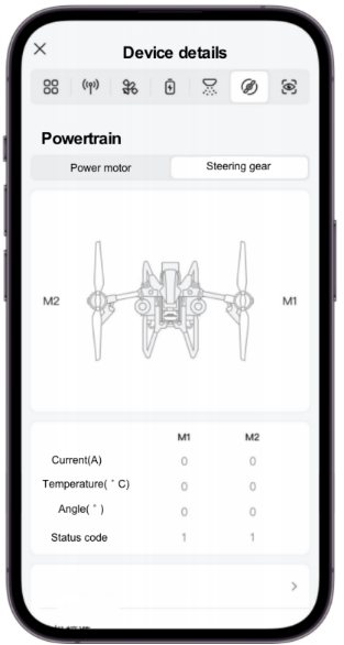
- Current: indicates the output current of the ESC, which varies with the load.
- Temperature: indicates the temperature of the steering gear.
- Angle: indicates the current tilt angle of the steering gear.
- Status code: indicates the current working status code of the steering gear.
Motion control principle
The generation of lift
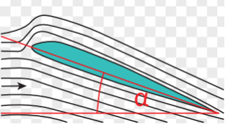
Elevation α
As shown in the above, the rotating propeller has an angle of Elevation α with respect to the air (usually the propeller rotates along the elevation,therefore to judge the rotating direction of it). At this time, the airflow of the upper curved surface is fast, the air pressure is low, while the lower surface airflow is slow and the air pressure is high which forms the pressure difference between the upper and lower propeller surfaces.And then generate the aerodynamic force to make the propeller upward to support the flight of the drone.
Principle of propeller arrangement
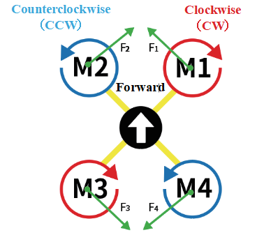
The propellers of the P100 Pro agricultural drone are arranged at four symmetrical corners. The propellers rotating counterclockwise are called CCW, and the ones rotating clockwise are called CW. Therefore, the propeller-driven by the M2 and M4 motors are CCW. The propellers driven by M1 and M3 motors are CW.
When the drone flies normally, according to Newton's third law of action and reaction, the motor drives the propellers to rotate, and the propellers also give the motor a torque in the opposite direction of rotation. Because that motor is fixed on the machine arm, the reverse torque force can act back to it. So, the CCW and CW propellers of the drone need to be arranged in turn as shown above to balance the reverse torque (F1, F2, F3, and F4 cancel each other out), then the drone’s heading is ensured to be stable.
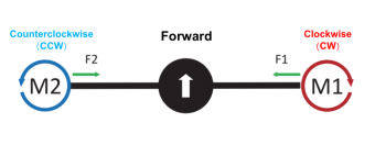
The propeller arrangement of V50 Pro agricultural drone is shown in the figure above, and the V-series drone’s propellers driven by M1 motor is CW and the propellers driven by the M2 motor is CCW.
Pitch/Roll/Altitude/Heading Control Philosophy
For the P100 Pro and V50 Pro agricultural drones, when the vertical lift force F1 is equal to the gravity force F2 of the drone, the height of the drone remains unchanged; when the vertical lift force F1 is greater than the gravity force F2 of the drone, the drone rises; when the vertical lift force F1 is less than the gravity force F2 of the drone, the drone descends.
For P100 Pro agricultural drone, when the speed of M3 and M4 motors is higher than that of M1 and M2 motors, the front side of the drone tilts downward.At this time, the lift force F perpendicular to the propeller rotation planeis also inclined, thus generating a vertical component force F1 and a horizontal component force F2. The vertical component force F1 balances the gravity of the drone, and the horizontal component force F2 pulls the drone forward.
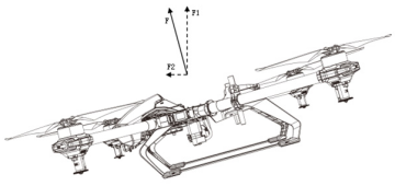
For V50 pro agriculture drone, when the M1 and M2 steering engines tilt forward, the propeller plane is driven to tilt forward. The lift force F perpendicular to the propeller rotation plane is then also inclined, thereby generating a vertical upward component force F1 and a horizontal forward component force F2, wherein the vertical component force F1 balances the gravity of the drone, the component force F2 in the horizontal direction pulls the drone forward.
For the P100 Pro agriculture drone, when the speed of M1 and M2 motors is higher than that of M3 and M4 motors, the rear side of the drone tilts downward. At this time, the lift force F perpendicular to the propeller rotation plane is also inclined, thus generating a vertical component force F1 and a horizontal component force F2. The vertical component force F1 balances the gravity of the drone, and the horizontal component force F2 pulls the drone backward.
For the V50 Pro agriculture drone, when the M1 and M2 steering engines tilt backward, the propeller plane is driven to tilt backward. The lift force F perpendicular to the propeller rotation plane is then also inclined, thereby generating a vertical upward component force F1 and a horizontal forward component force F2, wherein the vertical component force F1 balances the gravity of the drone, the component force F2 in the horizontal direction pulls the drone forward.
For the P100 Pro agricultural drone, when the speed of M1 and M4 motors is higher than that of M2 and M3 motors, the left side of the drone tilts downward. At this time, the lift force F perpendicular to the propeller rotation plane is also inclined, thus generating a vertical component force F1 and a horizontal component force F2. The vertical component F1 balances the gravity of the drone, and the other horizontal component F2 pulls the drone to fly to the left.
the For V50 Pro agricultural drone, when the speed of M1 motor is higher than that of M2 motor, the left side of the drone tilts downward. At this time, the lift force F perpendicular to the propeller rotation plane is also inclined, thus generating a vertical component force F1 and a horizontal component force F2. The vertical force component F1 balances the gravity of the drone, and the other horizontal force component F2 pulls the drone to fly to the left.
For the P100 Pro agricultural drone, when the speed of motors M2 and M3 is higher than that of motors M1 and M4, the right side of the drone tilts downward. At this time, the lift force F perpendicular to the propeller rotation plane is also inclined, thus generating a vertical component force F1 and a horizontal component force F2. The vertical component F1 balances the gravity of the drone, and the other horizontal component F2 pulls the drone to fly to the right.
For the V50 Pro agricultural drone, when the speed of motor M2 is higher than that of motor M1, the right side of the drone tilts downward. At this time, the lift force F perpendicular to the propeller rotation plane is also inclined, thus generating a vertical component force F1 and a horizontal component force F2. The vertical component F1 balances the gravity of the drone, and the other horizontal component F2 pulls the drone to fly to the right.
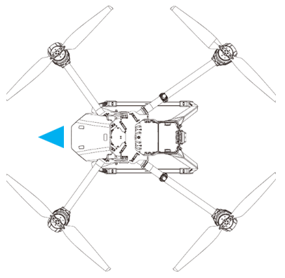
The heading of the 2023 agricultural drone, as the direction of the drone nose (blue arrow direction above).
Refer to the drawing of the P100 Pro agricultural drone propeller arrangement above, when the integral rotating speed of the motors M1 and M3 is greater than that of the motors M2 and M4, the resultant force of F1 and F3 is greater than that of F2 and F4, then the drone rotates counterclockwise; when the integral rotating speed of the motors M2 and M4 is greater than that of the motors M1 and M3, the resultant force of F2 and F4 is greater than that of F1 and F3, the drone rotates clockwise.
Refer to the drawing of the 2023 V50 Pro agriculture drone in chapter 2.1.3 above, when the M1 steering gear tilts forward and the M2 steering gear tilts backward, the M1 propeller tilts forward to generate an upward component force F1 and a forward component force F2., the M2 propeller tilts backward to generate an upward component force F1 and a forward component force F2. The component force F2 generated by the two propellers pulls the drone to rotate counterclockwise. When M1 steering gear tilts backward and M2 steering gear tilts forward, the M1 propeller tilts forward to generate an upward component force F1 and a backward component force F2, the M2 propeller tilts backward to generate an upward component force F1 and a forward component force F2. The component force F2 generated by the two propellers pulls the drone to rotate clockwise.
Integrated flight process
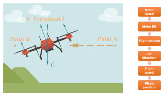
When the drone needs to fly from point A to point B, the action process of the drone is as follows:
(1) Adjust the rotating speed of the motor, make the rotating speed of the two motors near the point A side is faster than the two near the point B side.
(2) The change of motor speed difference brings about the change of motor lift difference, and the lift of drone near point A is larger than that near point B.
(3) The lift difference changes of the motor bring about the flight attitude changes, and the drone inclines downward near the B point side.
(4) The flight attitude changes bring about the direction changes of the overall lift (as shown in Figure 1 above, the direction of the lift F is inclined to point B). The drone generates a component force in the horizontal direction and simultaneously adjusts the rotating speed of the whole motor, which keep the vertical component force of the drone unchanged (balance the gravity of the drone itself).
(5) The component force in the horizontal direction causes the drone to generate acceleration in the horizontal direction, and finally change the position of the drone to move from point A to point B.
RTK positioning system
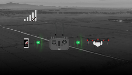
The RTK positioning system consists of a farmland mapping device (composed of an ARC3 Pro remote controller and a differential positioning module), a mobile base station and a fixed base station. It provides centimeter-level high-precision positioning for farmland mapping and drone flight. The accuracy of route planning reaches centimeter level, and at the same time, the high precision route flight of centimeter level is realized. The 2023 agricultural drone uses a dual-engine RTK module, and two antennas work at the same time. When the signal of any one of them is poor, the other one can still work continuously to ensure flight safety.
When the drone needs to fly from point A to point B, the action process of the drone is as follows:
(1) Adjust the rotating speed of the motor, make the rotating speed of the two motors near the point A side is faster than the two near the point B side.
(2) The motor speed difference changes bring about the motor lift difference change, and the lift of drone near point A is larger than that near point B.
(3) The lift difference changes of the motor bring about the flight attitude changes, and the drone inclines downward near the B point side.
(4) The flight attitude changes bring about the direction of the overall lift changes (as shown in Figure 1 above, the direction of the lift F is inclined to point B). The drone generates a component force in the horizontal direction and simultaneously adjusts the rotating speed of the whole motor, to keep the vertical component force of the drone unchanged (balance the gravity of the drone itself).
(5) The component force in the horizontal direction causes the drone to generate acceleration in the horizontal direction, and finally change the position of the drone move from point A to point B.
Composition of RTK positioning system
RTK Positioning System of P100 Pro Agricultural drone
Data Flow Analysis of RTK Positioning System
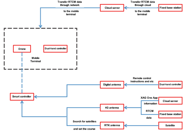
Positioning system data transmission flow
When the common satellite signal of mobile terminal (drone and mapper) of RTK host and the base station (mobile base station, fixed base station) is sufficient and stable, and the received RTCM differential data is stable and effective, the drone enters a real-time and high-precision positioning state. Therefore, there are two links in the positioning system of drone, one is the satellite search link of mobile terminal, and the other is the RTCM differential data communication link.
Satellite search link of the mobile station: The satellite search link of the drone is mainly realized through the RTK antenna at the drone end. The left and right RTK antennas on the fuselage can be responsible for drone satellite search and positioning, and the two RTK antennas are jointly responsible for obtaining the course of the drone. The satellite search work of the mapper is directly completed by the built-in antenna of the mapper.
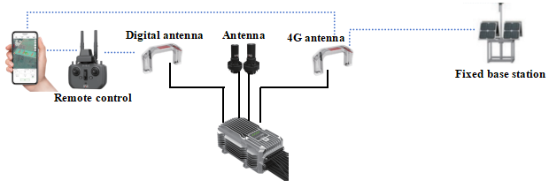
RTCM differential data transmission link: RTCM differential data is mainly transmitted from the base station to the mobile terminal. Among many ways for the base station to transmit data to the mobile terminal, there are mainly two ways to broadcast data to the drone and the mapper:
1.Directly broadcast data to the drone or handheld mapper through 2.4/5.8GHz dual-band antenna radio (broadcast distance is about 2km in radius);
2.The RTCM differential data is sent to the cloud server through its own network, and then is sent to the drone or a handheld map by cloud server through network.
Data Flow Analysis of Virtual RTK Positioning System
When there is no operator network signal in the drone operation plot, the drone can not connect to the fixed base station through the operator network. The 2023 agricultural drones carry a virtual RTK positioning. No RTK base station is required, it can carry out high-precision and precise operation without network.
Agricultural drones search satellites through RTK antennas, but the accuracy is poor because of the lack of high-precision base station assistance. At this time, a reference point is set for the agricultural drone or the ARC3 Pro remote controller. And then carry out convergence calculation relative to that reference point to enable the agricultural drone to enter the RTK. Set the reference point of the equipment as the datum point to cooperate with the operation correction function, can maintain the relative accuracy in centimeter level within a certain period of time.
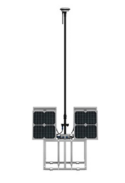
Fixed base station
When common satellite signal of mobile terminal(drone and mapper) of RTK host and the base station (mobile base station, fixed base station) is sufficient and stable, and the received RTCM differential data is stable and effective, the drone enters a real-time and high-precision positioning state. Therefore, there are two links in the positioning system of drone, one is the satellite search link of mobile terminal, and the other is the RTCM differential data communication link.
Introduction to RTK Parameter Interface of Positioning System
Positioning system parameter interface
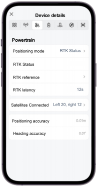
Heading accuracy: ≤ 2 ° required before takeoff and during flight
Number of satellites: ≥ 16 required before takeoff and during flight
Positioning mode and latency:
① NONE indicates no signal state (no GPS signal or too few GPS signals).
② Single stands for single point state (with GPS signal but without differential data).
③ Float indicates the floating state (the number of common satellites is insufficient, the common GPS signal is unstable, or the received differential data is unstable).
④ RTK indicates real-time and high-precision positioning status (common GPS signal is stable and the received differential data is stable).
⑤ RTK latency refers to the time difference from the last available differential data received by the drone to this moment. When the RTK latency is greater than 600 seconds, there will be a large deviation in the positioning accuracy of drone.
Principle of positioning system
The RTK system includes a GPS satellite data receiving part and an RTCM data (also called differential data) receiving part. GPS satellite data is mainly received by the two GPS antennas on the drone, and RTCM data can be received by radio (RF). That is, the 2.4G/5.8G antenna of the drone has an effective transmission radius of 2KM (the actual radius is affected by the actual environment). It can also be received through the 4G operator network, that is, the 4G antenna of the drone. Its effective transmission radius is 30 KM (the actual radius is affected by the actual environment).
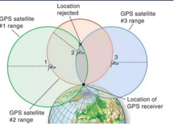
The GPS satellite data includes the number of the satellite, its orbital position, and the time at which the data was transmitted. RTK system calculates the distance to the satellite by the time of satellite data receiving and the length of time between satellite data instants (the signal transmission speed is known to be the speed of light). In this way, a sphere as shown can be built, which taking the orbital position of the satellite as center and the distance between the drone and the satellite as the radius.
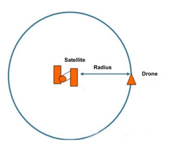
The RTK system can only know that the drone is located on the sphere above through the data transmitted by a satellite.It is impossible to determine which point on the sphere the drone is on.When the RTK system receives the data transmitted by three GPS satellites, it can form three spheres as shown in the following figure.The point at which these three spheres intersect determines the position of the drone on the Earth.
During the transmission of GPS satellite data to the drone, due to satellite clock error, ephemeris error, ionospheric error and tropospheric error, the positioning information obtained by drone from GPS satellite data deviates greatly from the actual position as a result. RTCM data is used to eliminate these errors and achieve centimeter-level positioning accuracy.
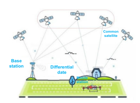
In addition to the drone, the RTK system also needs the cooperation of the base station, which includes the mobile base station and the fixed base station. Fixed base stations can autonomously generate RTCM data, and the RTCM data generated by it can be transmitted to the drone through 4G operator network. Mobile base station is used as an intermediate station when the drone is far away from the fixed base station, and the drone can not connect to it. The mobile base station receives RTCM data from the fixed base station and then transmits the RTCM data to the drone.
Finally, the drone calculates the GPS satellite data collected by itself and the RTCM data received in real time, to obtain accurate positioning results, and also the absolute position (including longitude, latitude and altitude) with the earth as the coordinate system.
Flight Control and Sensing System
The flight control system of the drone is equivalent to the pilot to the manned aircraft. It is the core system for drone to complete the whole flight process of take-off, air flight, mission execution and landing. The system can ensure the flight stability of the drone and reduce the operation difficulty for the operator, in order to improve the ability to perform tasks and flight quality, enhance flight safety, and reduce the burden on operators.
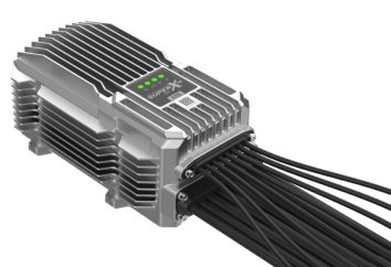
SUPERX4 ® Pro Flight Control
Principle of positioning system
The RTK system includes a GPS satellite data receiving part and an RTCM data (also called differential data) receiving part.GPS satellite data is mainly received by two GPS antennas on the drone, and RTCM data can be received by radio (RF).That is, the 2.4G/5.8G antenna of the drone has an effective transmission radius of 2KM (the actual radius is affected by the actual environment).It can also be received through the 4G operator network, that is, the 4G antenna of the drone.Its effective transmission radius is 30 KM (the actual radius is affected by the actual environment).
The GPS satellite data includes the number of the satellite, its orbital position, and the time at which the data was transmitted. RTK system calculate the distance to the satellite based on the time of receive satellite data,The distance to the satellite is calculated from the length of time between satellite data instants (the signal transmission speed is known to be the speed of light).In this way, a sphere with the orbit position of the satellite as the center and the radius as the distance between the drone and the satellite can be formed as shown in the following figure.
Connection between flight control and other modules
Flight control of P100 Pro agricultural drone
Data Flow Analysis of Flight Control and Sensing System
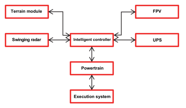
Intelligent flight of the drone is mainly realized through two data links of flight control. One is the control link of flight control, which realizes the control relationship between flight control and each system, and then the flight controller can control the flight altitude, speed and spraying amount of the drone according to the set task. The second is the perception link of flight control, which allows the drone to judge its own spatial position and surrounding environment through sensors, and let the drone get its own status in real time.
Flight control link: mainly realizes the control of communication system, powertrain and execution system by flight control. During operation, customer sets the flight parameters and spraying parameters in the ground station software, and uploads the parameters to the flight control through the communication system. After the drone takes off, the flight control will carry out precise flight and intelligent spraying according to the flight parameters and spraying parameters uploaded.
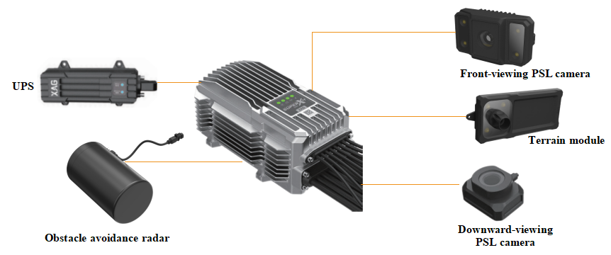
Flight control sensing link: The flight control sensing link mainly includes sensors like the built-in IMU, positioning system, PSL visual image module, swing radar module and terrain module. When drone is flying, the actual flight attitude and spatial position of drone can be obtained through IMU and positioning system, and provides data basis for the precise flight of drone. The PSL visual image module provides real-time images of the environment in front of and below the drone. At the same time, the swing radar will measure the distance between drone and surrounding obstacles in real time. When it is detected that the drone is too close to the obstacle, the flight control will plan a reasonable obstacle avoidance route, so as to achieve autonomous obstacle avoidance flight. The terrain module will measure the height of the drone to the ground and the displacement of the drone relative to the ground in real time, and then the drone can automatically adjust its flight height according to the ups and downs of the terrain. When the RTK positioning goes wrong, flight control will automatically switch to ground visual positioning to provide flight altitude and spatial location information for drone to ensure flight safety.
Introduction of Flight Control and Sensing System Module
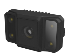
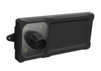
PSL camera
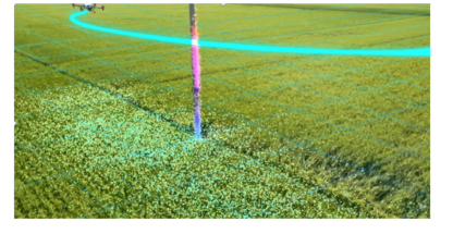
The PSL camera is composed of a forward-looking camera and a downward-looking camera, and the camera transmits images of the surrounding environment of the drone in real time through 4G network. The forward-looking camera is used to observe the environment in front of the drone, which is convenient for users to find environmental changes in time. The downward camera observes the environment below the drone. When the drone is used for mapping and dotting, the downward camera can be used to observe the boundary of the plot to ensure the safety of drone mapping.
Terrain module
The terrain module is composed of ground vision and terrain radar. The main function of the terrain radar is to detect the distance from the drone to the ground, to provide altitude data for terrain follow flight. The ground vision function is mainly used when the GPS positioning system has abnormal signal occlusion and interference. It provides auxiliary positioning function for drone and ensure flight safety.
Working principle of terrain radar: millimeter wave radar emits millimeter wave, and when the millimeter wave reaches the ground, it will reflect part of the millimeter wave back to the radar. When the millimeter wave radar receives the reflected millimeter wave, it can calculates propagation time of the millimeter wave and combined with the known speed of light to solve the relative height to the ground.
Working principle of ground-to-ground vision: the camera takes pictures of the ground continuously, and then extracts the feature points on the pictures, to determine the relative horizontal speed of the drone by comparing the movement of the feature points in the two pictures, to determine the relative horizontal speed of the drone, and then to determine the relative level of the drone according to the integral of the velocity.
Terrain radar is a kind of vertical positioning equipment, which can obtain the height of drone relative to the ground, and make the flying height of the drone can change correspondingly along with the fluctuation of the terrain. Ground vision is a kind of horizontal positioning, which can keep the horizontal position of drone stable.
Ground vision function and precautions:
When the positioning system goes wrong, the drone will enable the ground vision positioning and hovered in place for 2 minutes until the satellite recovered. If the satellite signal was not recovered, the drone would automatically land and the ground station will also automatically remind the seconds of landing. When the ground condition is not allowed to force landing, the ground station will also provide a pointing flight function, which can point the drone to land at the nearest safe place. During the process, the position information of drone is provided by ground vision, so do not point the drone to the non-textured environment such as water surface when pointing flight. The premise of using the ground-to-ground visual function is to accurately grasp the feature points on the ground. Therefore, attention should be paid to keeping the lens and LED fill light clean.
Obstacle avoidance radar
The swing radar senses spatial information by transmitting and receiving millimeter waves from multiple angles, and generates 4D spatial maps autonomously through intelligent cognitive algorithms. 4D is four dimensions, three of which are three-dimensional space. That is to say, the position of the drone relative to the obstacle in the three-dimensional space can be sensed. The other dimension is the speed of the drone relative to the obstacle. The swing radar can effectively identify the area between 4.92 ft and 262.4 ft in front of the agricultural drone. The horizontal angle of the field of view is ± 40 degrees, vertical angle is + 90 degrees to -45 degrees, and the distance, the position, the move direction and the speed of the obstacle can be accurately detected.
4D imaging radar
4D imaging radar
| Type Number | RD 24912 |
Work Consumption | 12W |
Way of perception | Milligram Meter-wave imaging, sending more and receiving more |
Perceptual parameters | Barrier Obstruction position, distance, direction of movement, relative speed |
Perception range | 4.92 ~ 262.4 ft |
Field of view ( FOV ) | Level ± 40 °, vertical + 90 ° ~ -45 ° |
Obstacle avoidance direction | Realized forward obstacle avoidance according to the flight direction |
Relative height of safety obstacle avoidance | ≥ 4.92 ft |
Obstacle size of safety obstacle avoidance | Diameter ≤ 5.9 in |
Distance of safety obstacle avoidance | 8.2 ft (the distance between the blade tip and the obstacle after the drone from braking to stable hovering) |
Electrical System
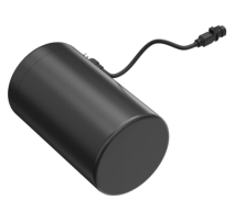
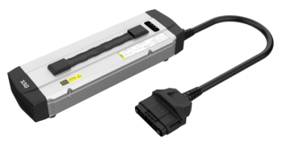
The B13970 smart battery uses high-density fast-charging core materials and has a 13-core/975 watt-hour/4.35 V industrial high-voltage core, which is compatible with the whole series of XAG agriculture drone. Equipped with XBMS intelligent power management system, the battery power is self-balanced, to ensure flight safety. At the same time, it is equipped with IP67 protection grade, which can charge the whole battery in water, cool the heat, charge on the ground and use it after charging with no need to wait. Therefore, two sets of batteries and one generator can work circularly. The 2023 XAG agricultural drone’s mart Battery uses high-density fast-charging core materials and smart chargers, which a B13970 battery can be charged fully in 11 minutes. Cooperate with GC6000 mobile overcharging station, a B13970 battery can be fully charged in 9 minutes.
B13970 Smart Battery
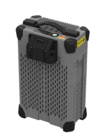
The CM13600 charger features a wide-voltage, self-cooled design. It has the functions of under-voltage protection, over-voltage protection, over-temperature protection and fault isolation. It belongs to the medium power charger. It can monitor the status information of all smart batteries in real time during charging.
CM13600 Charger
GC6000 mobile overcharging station combines power generation and charging into one. It is the most efficient, lightest and smallest gasoline generator of the same level on the market.It has excellent economical efficiency and portability.
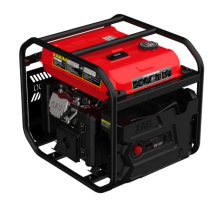
GC6000 mobile overcharging station
Battery interface parameters
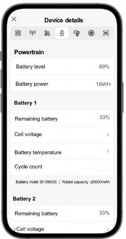
Cell voltage: standard voltage range is 43.2-56.5V
Battery temperature: battery chip temperature
Cycle count: indicates the times that the battery has undergone a complete charge and discharge cycle
Precautions
• When the battery temperature is higher than 60 ° C, there will be a high temperature reminder, and when the battery temperature is lower than 50 ° C, the reminder will be released.
• When the battery temperature is lower than 10 ° C, there will be a low temperature reminder, and when it is heated to 20 ° C, the reminder will be released.
• When a high temperature warning of the battery occur, it is forbidden to charge and discharge, and the battery can be used only after it is cooled in a cool place.
• When a low temperature warning of the battery occur, the battery needs to be heated, and the heating methods are divided into automatic heating and manual heating. The battery can be used when it is heated to 20 ° C.
• The maximum capacity of the battery decreases as the Cycle count increases.
Execution System
RevoSpray system
RevoSpray system is the execution system of 2023 agricultural drone, which consists of a medicine box, a spraying pipeline, a peristaltic pump, a centrifugal nozzle and a spraying wire collecting plate. The P100 Pro agricultural drone uses a high-frequency pulse peristaltic pump, increasing the spray flow rate to 5.72 gal/min (the V50 Pro spray rate is 3.12 gal/min) , while using self-growing materials to completely avoid the risk of pump pipe blockage.
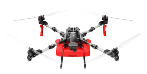
P100 Pro Agricultural drone RevoSpray System
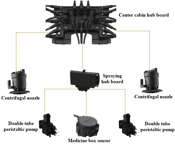
Module connection of RevoSpray system
RevoSpray system is the execution system of 2023 agricultural drone, which consists of a medicine box, a spraying pipeline, a peristaltic pump, a centrifugal nozzle and a spraying wire collecting plate. The P100 Pro agricultural drone uses a high-frequency pulse peristaltic pump, increasing the spray flow rate to 5.72 gal/min (the V50 Pro spray rate is 3.12 gal/min) , while using self-growing materials to completely avoid the risk of pump pipe blockage.
Link Diagram of the V50 Pro agricultural drone RevoSpray system
Data flow analysis of RevoSpray system
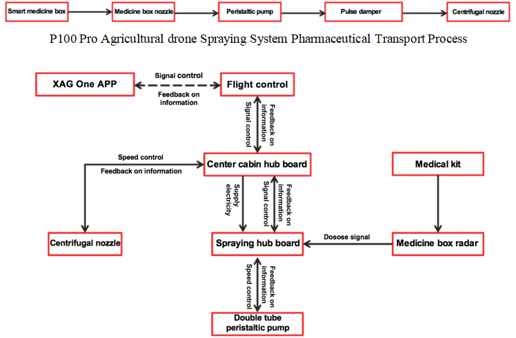
Signal transmission process of spraying system
The drone’s spraying system mainly realizes its function through two links, one is the liquid medicine circulation link, which the liquid medicine flows in from the medicine box and flows out through the nozzle. The other is a spraying control link, which controlling the spraying dosage and the spraying range of the drone, do that the drone can achieve accurate spraying.
Liquid medicine circulation link: under the action of pressure, the liquid medicine in the box flows through a filter at the bottom of the box, shunted from the nozzle, then enters the two peristaltic pumps. The liquid medicine passes the peristaltic pumps through a pulse damper, and then flows into the nozzle to spraying out.
Spraying control link: the smart medicine box chest transmits the liquid medicine information to the drone through the medicine chest radar, and transmitted to the center cabin hub board through the 12PIN load line, and then to the flight control.The flight control transmits the atomization level and the flow rate command to the center cabin hub board, and the center cabin hub board transmits the command to the spraying line wiring board.The spraying wiring board transmits a flow instruction to the peristaltic pump, and the peristaltic pump controls the flow speed of the liquid medicine by extruding the liquid medicine, so as to control the spraying dosage. Finally, the liquid medicine is atomized by the spray nozzle in a high-speed centrifugal mode, and matched with the downward pressure wind field generated by the propeller, the liquid medicine is evenly sprayed on the surface of the plant. During the drone flight, the center cabin hub board distributes the power to the spraying line collection plate and the centrifugal nozzle, then the spraying wiring board then distributes the power to the peristaltic pumps and the medicine box radar.
Introduction to the module
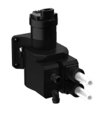
Peristaltic pump
The working principle of the peristaltic pump is that, by repeatedly compressing the elastic tube, to make the liquid in the tube move in a certain direction (the flow rate is determined by the diameter of the tube and the compression speed), just like two fingers squeezing a hose full of liquid, with the movement of the fingers, a negative pressure is formed in the tube, and the liquid flows with it. P100 Pro double pump tube peristaltic pump adds a pump tube on this basis to make the flow larger. The peristaltic pump is the power source of the spraying system, which continuously sucks the liquid medicine out of the medicine box and transmit to each spray head.
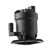
Nozzle
The centrifugal nozzle consists of a centrifugal motor and a centrifugal spray disc. The motor provides centrifugal force for atomization, which has powerful torque under high-speed rotating. The centrifugal spray plate throws away the liquid medicine to achieve effective atomization.
Introduction to health value parameter
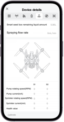
• The health value represents the pumping capacity of the pump pipe, with a smaller value indicating a weaker pumping capacity.The health value will gradually decrease with the use of wear, corrosion, aging and other factors.
• "Pump calibration" can correct or improve the health value, when the pump calibration is carried out, the value is still lower than the standard value, it means that the pump water capacity is weak, and the pump pipe loss is serious and needs to be replaced.
• The standard value of P100 Pro pump tube health value is between 2.1 to 3.0 (the standard value of V50 Pro pump tube health value is between 1 to 1.6). If the value is too small or too large, it will affect the spraying amount, so it is necessary to check the peristaltic pump pipe in time, add lubricating oil and re-calibrate the spraying. If the difference is still large after calibration, the peristaltic pump tube can be replaced.
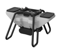
RevoCast System
RevoCast system is the execution system of P100 Pro and V50 Pro agricultural drones, which consists of a seed box, a spreading wiring board, a spiral feeding device and a throwing disc. The seeds and solid particles can be accurately sowed to the required position. Equipped with small, medium, large and super large four different augers for different solid particles can ensure efficiency while making the scattered particles not agglomerated and adhered. The high-speed throwing disc can ensure the sowing width and accuracy, to meet the needs of spreading.
XAG RevoCast P3

XAG RevoCast V3
Spreading system module connection
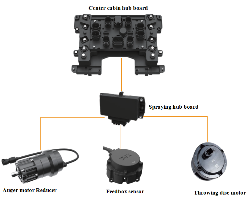
P100 Pro Agricultural drone Spreading System Link Diagram
Data flow analysis of RevoSpray system
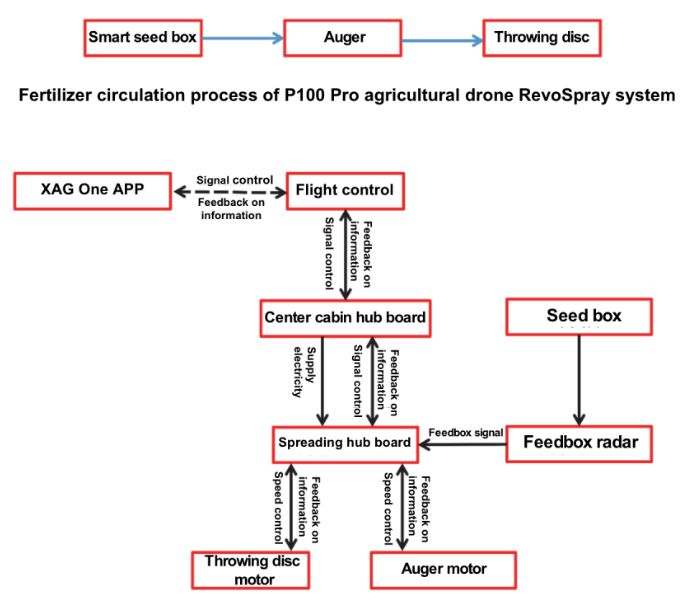
Signal Transmission Process of P100 Pro Agricultural drone RevoSpray System
The RevoSpray system is mainly realized by two parts: one is a spiral feeding device, which mainly used to precisely control the target output of solid particles.The second is the high-speed throwing disc, which mainly rotates the throwing disc at a high speed to generate centrifugal force to throw away the seeds, to ensure the uniformity of distribution within the dispersion range.
Module Introduction
Spiral Feeder Device
The auger has a spiral structure and is divided into extra-large, large, medium and small sizes.Whenever the auger rotates, the solid particles inside the auger will be pushed to the throwing disc. The required amount of each spreading can be accurately controlled by controlling the rotating speed of the packing auger.
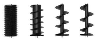
Auger model
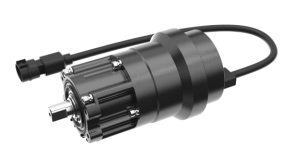
Auger motor
Material level sensor
It is used to assist the broadcast system to determine the particle situation in the seed box.
Material level sensor
High-speed centrifugal throwing disk
Throwing disc motor: control the centrifugal force when the throwing disc rotates by changing the rotating speed.
Throwing disc: unique seed protection design, can be both efficient and accurate while not damaging the seed.
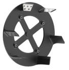
Throwing disc