Chapter 4 Agricultural Drone Aircraft Damage/Fault Isolation
Overview
Fault damage maintenance manual is an important technical document for judging and troubleshooting equipment faults. It provides the necessary technical data and replacement standards for identifying and analyzing faults and helps maintenance engineer to troubleshoot faults. It is suitable for daily maintenance inspection and testing, daily equipment maintenance. The manual is designed to find the fault in the most effective way and take necessary measures to eliminate the fault, so that the equipment can return to normal state and quickly resume operation. The manual will be constantly updated and improved as the equipment is iterated. This chapter includes damage inspection and test guidelines and specifications, inspection requirements of appearance and basic operation damage, requirements of equipment replacement, terminology interpretation, appearance and basic operation damage inspection standards, appearance and structural parts replacement standards, damage inspection test guidelines and specifications.
Damage Inspection and Testing Guidelines and Specifications
Applicable Models and Equipment
XAG Agricultural Drone
XAG RevoSpray System/RevoSpray System
Definition of The Engineer's Responsibilities
Maintenance engineers are responsible for the maintenance and management of the received equipment. If it is necessary to hand over the equipment under maintenance, the engineers should sort out the abnormal information of the equipment, maintenance progress, matters need attention and other files and materials, and check with the receiving engineer during the handover.
Maintenance Responsibility
Ensure repair and maintenance in time.
Ensure the integrity of the equipment after repair and maintenance.
Maintenance Responsibility
Ensure store equipment properly.
Ensure the integrity of the equipment.
Ensure the integrity of the handover information.
Required Tools | ||||
Hexagon socket screwdriver | Electric screwdriver | Wrench | Torque wrench | Vice/needle nose pliers |
Sleeve | Multimeter | Wire cutters | Electrical tape | Acetic acid tape |
Cable tie | Flashlight | Rust remover |
|
Wearing requirements
Do not wear slippers during maintenance. Please wear protective gloves when cleaning seriously polluted drone or equipment during daily maintenance.
Inspection requirements for Appearance and Foundation Operation Damage
Environment Check and Storage Requirements
Make sure the room is well lit. The drone should be placed in the designated maintenance area and maintenance stand during the maintenance process. The disassembled small parts should be placed in containers such as storage box. Keep the electrical equipment away from water, and do not place it randomly. Sharp and vulnerable parts should be wrapped or protected with foam after disassembly.
Software Equipment Requirements
XAG 22/23 Agricultural Drone | XAG One App | 22 Simplified Platform (Partially applicable) | Motor maintenance detector |
XAG 21/XP Series Agricultural Drone | XAG One App | 21 Simplified Platforms (Partially applicable) |
Testing Requirements for electrical equipment and system failure
Test Environment and Storage Requirements
Make sure the room is well lit. The drone should be placed in the designated maintenance area and maintenance stand during the maintenance process. The disassembled small parts should be placed in containers such as storage box. Keep the electrical equipment away from water, and do not place it randomly. Sharp and vulnerable parts should be wrapped or protected with foam after disassembly.
Software Equipment Requirements
XAG 22/23 Agricultural Drone | XAG One App | 22 Simplified Platforms (Partially applicable) | Motor maintenance detector |
XAG 21/XP series Agricultural Drone | XAG One App | 21 Simplified Platform (Partially applicable) |
|
Flight control and battery | 21/22 Simplified Platform | Flight control test fixture | Battery load tester |
Requirements For Returning Electrical Equipment To Warehouse
Status Check
Appearance
• Check whether there is open compromise that affects its safety.
• Check whether there is damage of fixation.
Function
• Check whether the system functions are inoperable.
• Check whether the system function has errors and has not been improved after upgrading.
• Check whether there is any damage or failure of the movement mechanism in the electrical element.
Identification of return
Fill in the required information according to the return policy.
Glossary
Crack
Cracks in materials under the action of stress or environment (or both) are one of the important performance indicators of materials. The appearance and expansion of cracks make the mechanical properties of the material significantly worse.
Ductile Crack/Dehiscence
A ductile crack is also called a ductile fracture. Ductile fracture is accompanied by obvious plastic deformation and forms a ductile fracture (the fracture surface is perpendicular or inclined to the tensile stress, and it has a fine bump and bump, which is fibrous). In ductile fracture, extensive plastic deformation (necking) occurs before fracture. Ductile fracture describes the ultimate failure of a ductile material that subjected to tension. The material does not break, but rather "pulls apart," often leaving a rough surface. In this case, there is slow growth and the absorption of large amounts of energy before the rupture.
Penetrating Crack/Dehiscence
The penetrating crack is through the entire member. The crack extending to more than half of the thickness is often regarded as a penetrating crack and treated as an ideal tip crack, that is, the radius of curvature of the crack tip tends to zero. It can be straight lines, curves and other shapes.
Nick
Nicks are generally caused by scratches or cuts on the surface of the workpiece by sharp objects. Notches generally do not cause penetrating damage, but the generation of notches may lead to oxidation or corrosion reactions inside the workpiece in contact with the environment, resulting in cracking.
Piercing
Perforation is a phenomenon that penetrates the surface of an object by drilling, chiseling, or being hit by a sharp object. Irregular perforation will induce the formation of cracks. Perforation will affect the mechanical properties of the original object and induce deformation of the object.
Stress Whitening
Stress whitening is a kind of whitening phenomenon of polymer caused by external force deformation. Under the action of external force, there are holes, fractures, delamination, and other phenomena in the material. Materials with stress whitening (plastics, rubber, etc.) will lose their original mechanical properties and cause fracture.
Wire Sheath
The wire sheath is made of plastic or rubber. Some of the rubber is covered with fiber, which is used to wrap the wire for insulation and protection of the internal core.
Wire Core
The wire core is a wire wrapped in the wire sheath The conduction of current and signal in the device will be transmitted through the wire core. The wire core is divided into single strand and multiple strands. Multiple strands are generally used in drone equipment. When the wire core is exposed to the environment, it will be corroded. When the positive and negative wires in the power supply cable are short-circuited, it will cause a short circuit leading to fire or physical damage to the electronic equipment.
Contact Piece
Contact pieces are commonly used on equipment that is closed for long-term maintenance and requires communication or power. Contact pieces are generally made of copper and has high plasticity. In the closed state, the contact piece and the contact piece can be closely attached to ensure the tightness.
Ablation
Ablation is caused by the contamination of contact piece with foreign matter and partial high temperature as the contact piece can be easily affected by wear or arc in long-term use. The ablation is manifested as blackening of the contact surface, increased thickness of foreign matter and increased resistance.
Damage Inspection Standard for Appearance and Foundation Operation
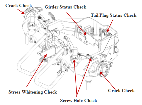
Examination of damage to the middle part of the head and the tail frame
P80 Damage Inspection of Head, Middle Part and Tail Frame
Verify whether the equipment shows the following damage. In case of any damage that is not in this list and affects the operation safety, the equipment shall be replaced after report and verification.

• Stress whitening of the structure greater than 0.4in with cracking or deformation.
• The middle and tail frame girders were deformed, cracked and could not be fixed.
• The screw hole slips, cannot be fixed or cracks.
• Single tail contact is ablated (ablation area greater than 30%).
• Two or more trailing contacts are ablated (ablation area greater than 20%).
• An open crack of greater than 0.4in in the sheath of the stub cable with the core broken.
• The gap of tail patch cable sheath is more than 0.2in.
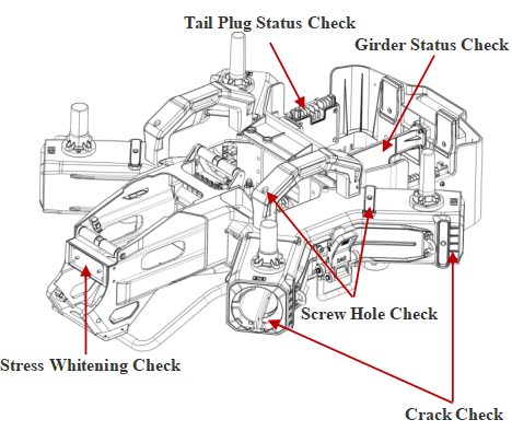
V40 damage inspection of middle head and tail frame
Verify whether the equipment shows the following damage. In case of any damage that is not in this list and affects the operation safety, the equipment shall be replaced after report and verification.
• Stress whitening of the structure greater than 0.4in with cracking or deformation.
• The middle and tail frame girders were deformed, cracked and could not be fixed.
• The screw hole slips, cannot be fixed or cracks.
• Single tail contact is ablated (ablation area greater than 30%).
• Two or more trailing contacts are ablated (ablation area greater than 20%).
• Tail contact is missing, deformed, or loose.
• An open crack of greater than 0.4in in the sheath of the stub cable with the core broken.
• The gap of tail patch cable sheath is more than 0.2in.
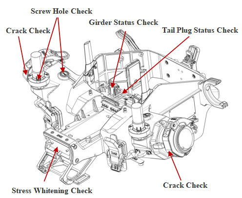
P100 Damage Inspection of Head, Middle Part and Tail Frame
Verify whether the equipment shows the following damage. In case of any damage that is not in this list and affects the operation safety, the equipment shall be replaced after report and verification.
• Stress whitening of the structure greater than 0.4in with cracking or deformation.
•The middle and tail frame girders were deformed, cracked and could not be fixed.
•Single tail contact is ablated (ablation area greater than 30%)
• Two or more trailing contacts are ablated (ablation area greater than 20%).
• Tail contact is missing, deformed, or loose.
• An open crack of greater than 0.4in in the sheath of the stub cable with the core broken.
•The gap of tail patch cable sheath is more than 0.2in.
V50 Damage Inspection of Head, Middle Part and Tail Frame
Verify whether the equipment shows the following damage. In case of any damage that is not in this list and affects the operation safety, the equipment shall be replaced after report and verification.
• Stress whitening of the structure greater than 0.4in with cracking or deformation.
•The middle and tail frame girders were deformed, cracked and could not be fixed.
•Single tail contact is ablated (ablation area greater than 30%)
• Two or more trailing contacts are ablated (ablation area greater than 20%).
• Tail contact is missing, deformed, or loose.
• An open crack of greater than 0.4in in the sheath of the stub cable with the core broken.
•The gap of tail patch cable sheath is more than 0.2in.
P100 Pro Damage Inspection of Head, Middle Part and Tail Frame
Verify whether the equipment shows the following damage. In case of any damage that is not in this list and affects the operation safety, the equipment shall be replaced after report and verification.
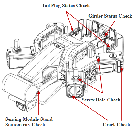
• Stress whitening of the structure greater than 0.4in with cracking or deformation.
•The middle and tail frame girders were deformed, cracked and could not be fixed.
• Single tail contact is ablated (ablation area greater than 30%)
• Two or more trailing contacts are ablated (ablation area greater than 20%).
• An open crack of greater than 0.4in in the sheath of the stub cable with the core broken.
•The gap of tail patch cable sheath is more than 0.2in.
• Sensing module support is loose with cracks greater than 0.4in or stress whitening.
V50 Pro Damage Inspection of Head, Middle Part and Tail Frame
Verify whether the equipment shows the following damage. In case of any damage that is not in this list and affects the operation safety, the equipment shall be replaced after report and verification.

• Stress whitening of the structure greater than 0.4in with cracking or deformation.
• Deformation and cracking of folding structure and locking structure in the middle.
• The screw hole slips, cannot be fixed or cracks.
• Single tail contact is ablated (ablation area greater than 30%)
• Two or more trailing contacts are ablated (ablation area greater than 20%).
• An open crack of greater than 0.4in in the sheath of the stub cable with the core broken.
• Sensing module support is loose with cracks greater than 0.4in or stress whitening.
Damage Inspection for Power Supply Cable of Busbar and Central Compartment
P80 Damage Inspection of Power Supply Cable of Busbar and Center Compartment
Verify whether the equipment shows the following damage. In case of any damage that is not in this list and affects the operation safety, the equipment shall be replaced after report and verification.
• The waterproof glue is broken off, perforated and missing.
• The bus plate port is ablated.
• The collector plate is loose or deformed.
• The damage of cable sheath is more than 0.4in and the wire core is exposed.
• The wire core shows open or hidden fracture.
V40 Damage Inspection of Power Supply Cable of Busbar and Center Compartment
Verify whether the equipment shows the following damage. In case of any damage that is not in this list and affects the operation safety, the equipment shall be replaced after report and verification.
• The waterproof glue is broken off, perforated and missing.
• The bus plate port is ablated.
• The collector plate is loose or deformed.
• The damage of cable sheath is more than 0.4in and the wire core is exposed.
• The wire core shows open or hidden fracture.
P100 Damage Inspection of Power Supply Cable of Busbar and Center Compartment ( universal for 22/23 models)
Verify whether the equipment shows the following damage. In case of any damage that is not in this list and affects the operation safety, the equipment shall be replaced after report and verification.
• The waterproof glue is broken off, perforated, and missing.
• Cracked or missing manifold plate screw holes.
• The bus plate port is ablated.
• The collector plate is loose or deformed.
• The damage of cable sheath is more than 0.4in and the wire core is exposed.
• The wire core shows open or hidden fracture.
V50 Damage Inspection of Power Supply Cable of Busbar and Center Compartment (22/23 models universal)
Verify whether the equipment shows the following damage. In case of any damage that is not in this list and affects the operation safety, the equipment shall be replaced after report and verification.
• The waterproof glue is broken off, perforated, and missing.
• Cracked or missing manifold plate screw holes.
• The bus plate port is ablated.
• The collector plate is loose or deformed.
• The damage of cable sheath is more than 0.4in and the wire core is exposed.
• The wire core shows open or hidden fracture.
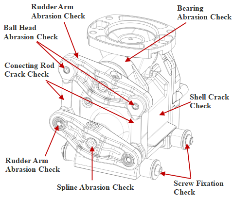
Damage Inspection of Steering Gear
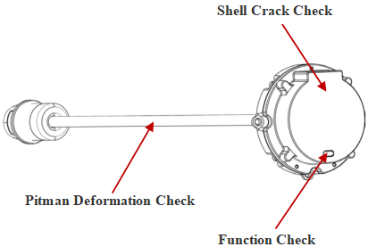
V40 Damage Inspection of Steering Gear
Verify whether the equipment shows the following damage. In case of any damage that is not in this list and affects the operation safety, the equipment shall be replaced after report and verification.

• The shell of steering gear shows penetrating crack of more than 0.2in.
• The shell of steering gear shows cracks greater than 0.4in with stress whitening.
• The fixing screw hole on the steering gear shows penetrating crack larger than 2mm.
• The spline shaft of the steering gear or motor base has a penetrating crack of more than 2mm.
• The spline teeth of the steering gear or motor base are worn by more than 30% (the wear depth is more than 1mm).
• After the spline of the steering gear or motor base is fixed with the rudder arm, it is still loose (left and right and front and back shaking is obviously loose).
• The steering gear cannot operate normally.
V50 Damage Inspection of Steering Gear
Verify whether the equipment shows the following damage. In case of any damage that is not in this list and affects the operation safety, the equipment shall be replaced after report and verification.
• The shell of steering gear shows penetrating crack of more than 0.2in.
• The shell of steering gear shows cracks greater than 0.4in with stress whitening.
• The fixing screw hole on the steering gear shows penetrating crack larger than 2mm.
• The spline shaft of the steering gear or motor base has a penetrating crack of more than 2mm.
• The spline teeth of the steering gear or motor base are worn by more than 30% (the wear depth is more than 1mm).
• After the spline of the steering gear or motor base is fixed with the rudder arm, it is still loose (left and right and front and back shaking is obviously loose).
• The steering gear cannot operate normally.
Damage Inspection of Propeller
Damage Inspection of Propeller (21/22/23 models Universal)
Verify whether the equipment shows the following damage. In case of any damage that is not in this list and affects the operation safety, the equipment shall be replaced after report and verification.
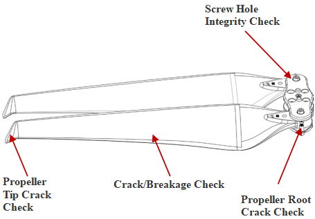
• Cracking or breakage of blades greater than 0.2in.
• The blade is deformed, and the tip deviation is greater than 30 mm.
• Longitudinal cracking greater than 0.2in in the root.
•The root of the propeller was more than 0.2in transverse cracking with more than 2mm depth cracking.
• The root of the propeller is broken by layers or the steel sleeve is loose.
Paddle clamp damage inspection
Damage Inspection of Propeller (applicable to 23 module)
Verify whether the equipment shows the following damage. In case of any damage that is not in this list and affects the operation safety, the equipment shall be replaced after report and verification.
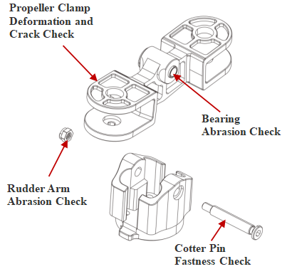
• Pin is loose and falls off.
• The propeller clamp is deformed.
• The propeller clamp has a longitudinal crack greater than 0.2in
• The bearing of blade clamp is worn and loose.
• The anti-loosening glue of pin nut is loose.
Damage Inspection for Power Electric Speed Control (ESC)
Damage Inspection of Power ESC (21/22/23 models universal)
Verify whether the equipment shows the following damage. In case of any damage that is not in this list and affects the operation safety, the equipment shall be replaced after report and verification.
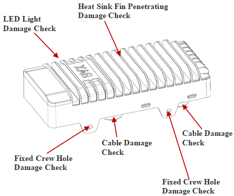
• The sheath of the power supply cable has an open break of more than 0.4in with the core broken.• The sheath of power supply cable is cracked by more than 0.2in.
• The sheath of a three-phase cable shows open crack more than 0.2in with a core broken.
• The OT terminal melted and affected the tightness and the contact piece is broken or missing .
• The surface area of a single contact is more than 20% ablated, missing or deformed.
• The hole of the fixing screw on ESC shell is damaged.
• ESC shell shows penetrating crack greater than 0.4in or a hole greater than 0.2in.
• The electric regulator fails to operate normally.
Damage Inspection of Power Motor
Damage Inspection of Power Motor (21/22/23 models universal)
Verify whether the equipment shows the following damage. In case of any damage that is not in this list and affects the operation safety, the equipment shall be replaced after report and verification.
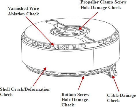
• The sheath of the power supply cable has an open break of more than 0.4in with the core broken.• The sheath of power supply cable is cracked by more than 0.2in.
• The sheath of a three-phase cable shows open crack more than 0.2in with a core broken.
• The OT terminal melted and affected the tightness and the contact piece is broken or missing .
• The surface area of a single contact is more than 20% ablated, missing or deformed.
• The hole of the fixing screw on ESC shell is damaged.
• ESC shell shows penetrating crack greater than 0.4in or a hole greater than 0.2in.
• The electric regulator fails to operate normally.
Damage Inspection of Motor Base
Damage Inspection of Motor Base (21/22/23 models universal)
Verify whether the equipment shows the following damage. In case of any damage that is not on this list and affects the operation safety, the equipment shall be replaced after report and verification.
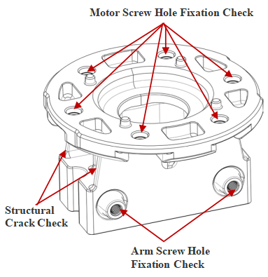
• The screw hole on motor base shows a penetrating crack of more than 0.12in.
• Penetrating cracks greater than 0.12in on the motor base surface.
• Cracks greater than 0.2in with stress whitening on motor base.
• The motor base is deformed and cannot be assembled with the motor or the arm.
Damage Inspection of Arm
Damage Inspection of Arm (21/22 models universal)
Verify whether the equipment shows following damage. In case of any damage that is not in this list and affects the operation safety, the equipment shall be replaced after report and verification.
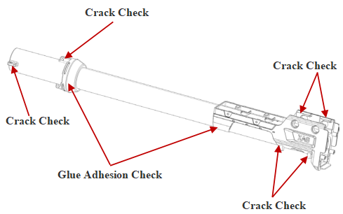
• Ductile crack greater than 0.2in in the end section of the arm.
• Penetrating crack or perforation larger than 0.2in at any position of the arm.
• The arm shows significantly bent and has an error of more than 0.4in compared to the complete arm.
• Cracks or looseness greater than 0.2in at the glue holding position of the arm.
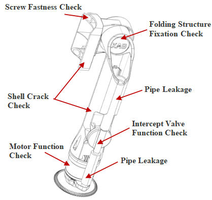
Damage Inspection of Arm (23 model)
Verify whether the equipment shows the following damage. In case of any damage that is not in this list and affects the operation safety, the equipment shall be replaced after report and verification.
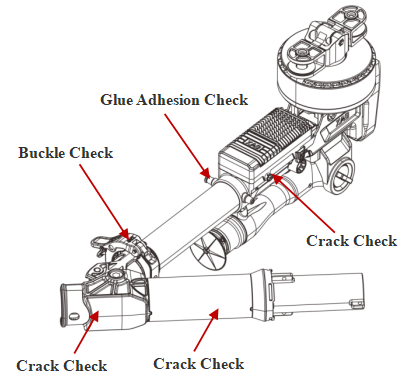
• Ductile crack greater than 0.2in in the end section of the arm.
• Penetrating crack or perforation larger than 0.2in at any position of the arm.
• The arm shows significantly bent and has an error of more than 0.4in compared to the complete arm.
• Cracks or looseness greater than 0.2in at the glue holding position of the arm.
• The arm hoop is not broken or missing.
• The folding structure of the arm shall no cracks larger than 0.4in and deformation.
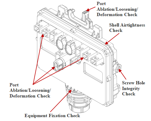
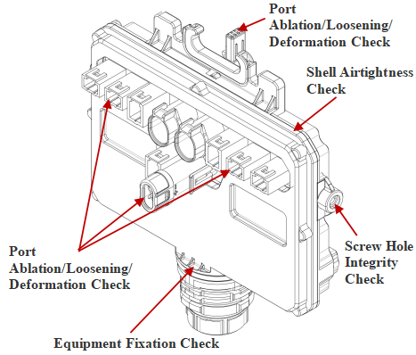
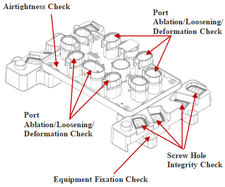
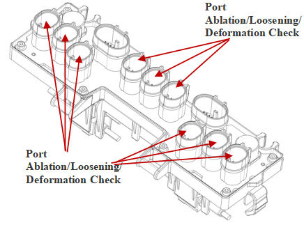
Damage Inspection of Flight Control and Sensing System
Verify whether the equipment shows the following damage. In case of any damage that is not in this list and affects the operation safety, the equipment shall be replaced after report and verification.
• the sheath of the cable shows an open crack greater than 0.4in in with core broken.
• The crack of cable sheath is greater than 0.2in.
• The fixing screw hole on the housing is damaged.
• Penetrating crack of the housing is greater than 0.4in.
• Perforation of the housing greater than 0.2in.
• The equipment fails to operate properly.
Appearance Damage Inspection Standard of Perform System
Appearance Damage Inspection Standard of RevoSpray Key Structure
Damage Inspection of RevoSpray System (21/22 universal)
Verify whether the equipment shows the following damage. In case of any damage that is not in this list and affects the operation safety, the equipment shall be replaced after report and verification.
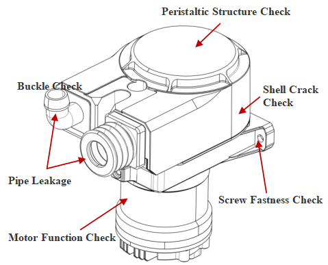
• Pesticides container starts to leak, and peristaltic pump cannot be fixed firmly.
• The peristaltic pump cannot be fixed firmly, and the infusion tube leaks.
• Peristaltic pump has a penetrating crack greater than 0.4in.
• Peristaltic pump housing shell perforation greater than 0.2in.
• The spray rod has fallen off, failed, or deformed.
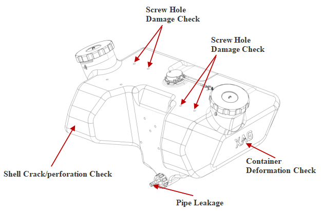
Precautions
• A nut has been inserted into the screw hole to fix the pesticides container. If the nut is not firmly fixed, check whether the nut in the screw hole is fastened. If the nut falls off, use a rubber mallet to insert the nut into the hole and use epoxy glue or quick-drying glue to reinforce the nut and reinstall the screw.
• If the nut of the pesticides container is loosened and the container is deformed, it should be repaired first. It is forbidden to replace the pesticides container directly without repairation.
Appearance Damage Inspection Standard for RevoCast Key Structure
Damage Inspection Standard for RevoCast (22/23 model universal)
Verify whether the equipment shows the following damage. In case of any damage that is not in this list and affects the operation safety, the equipment shall be replaced after report and verification.
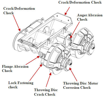
• Leakage occurs in the feedbox, and the spreading module cannot be fixed.
• RevoCast gear group is damaged (the gear is damaged and fails). .
• The Auger motor has a rust failure (the rust area is greater than 30% and the motor fails to operate).
• The main body of Auger is worn by more than 0.2in with material leakage.
• Flange area is more than 30% rust and affect the stability of fixing and operation. .
• The throwing disk motor shows penetrating crack or structural damage greater than 0.4in.
• The Throwing disc motor has an area of more than 30% rust and affects the operation of the motor.
• The wire sheath is cracking and damaged with a core fracture or 0.2in sheath worn-out.
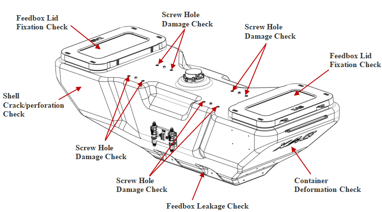
Precautions
A nut has been inserted into the screw hole to fix the feedbox. If the nut is not firmly fixed, check whether the nut in the screw hole is fastened. If the nut falls off, use a rubber mallet to insert the nut into the hole and use epoxy glue or quick-drying glue to reinforce the nut and reinstall the screw.
• If the nut of the feedbox is loosened and the feedbox is deformed, it should be repaired first. It is forbidden to replace the feedbox directly without repairation.