Chapter 5 Disassembly and Assembly of XAG Agricultural Drone
Overview
The content of this chapter is mainly about the key components disassembly of 2023 P100Pro and V50Pro Agricultural Drone and their related mission system. Some of the content applies to 2022 P100 and V50 Agricultural Drone and their related mission systems. In this chapter, the disassembly process will be presented in graphical process combined with the corresponding serial number. Most of the installation process is the direction of the disassembly process. However, the installation sequence of some structures is different from the disassembly sequence. At the same time, before disassembling the structure and related electronic components, ensure that the power supply cables, communication cables, and pipelines have been separated, and cut off power supply in any form.
Disassembly Requirements
Before disassembly, the damage of the equipment should be inspected, and the maintenance plan should be brought forward. The electronic parts should be tested by testing software or fixture. Test software and fixtures should be used in strict accordance with the Module Test Manual and replace after confirming failure or abnormal function. The structural parts should be replaced according to the "Structural Damage Isolation Manual" after verifying the damage, confirming the composite replacement standard or confirming that the damage will cause a safety risk to the equipment.
Disassembly and Assembly Environment
The disassembly and assembly process must ensure that the room is well lit, and the maintenance process should be carried out by placing the Drone in the designated maintenance area and maintenance platform. Disassembled small parts should be placed in containers such as storage boxes. Electrical equipment should be stored away from water sources and should not be placed at will. Sharp and vulnerable parts shall be placed after being wrapped or protected with foam after removal.
Disassembly Preparation
After the Drone or related mission system has been verified and the maintenance plan has been formulated, the surface of the Drone or related mission system that needs to be disassembled shall be cleaned before disassembly. The relevant parts contacted with pesticides or fertilizers should be cleaned and disassembled after the basic cleaning is completed and air dried.
Disassembly and Assembly Tool List
Disassembly tools are necessary tools in the disassembly of Drone, including hand tools, power tools, calibration tools, auxiliary tools and consumables. The tool has certain risks in use. Therefore, you must strictly follow the Tool Usage Guide when using the tool to avoid personal or property loss caused by wrong operations.
Category | Tool Name | Specification | Applicable Scenarios |
Hand tools | Hexagon socket screwdriver | 1.5/ 2.0 /2.5/ 3.0/ 5.0 | Disassembly and assembly of drone |
| Ratchet wrench | - | Disassembly and assembly of drone |
Power tools | Electric screwdriver | 12V ~ 24V replaceable bit | Disassembly and assembly of drone |
Calibration tool | Torque wrench | Electronic torque wrench | Torque calibration of measurement and control points after installation |
Auxiliary tools | Corner device | - | Assemble and disassemble screws in narrow space with electric screwdriver |
Category | Tool Name | Specification | Applicable Scenarios |
Auxiliary tools | Wire guide | - | guide cable for arm and narrow position |
Consumables | Acetic acid tape | - | Wear-resistant wrapping for cables and pipes |
| Electrical tape | - | Repair of small cable (non-power supply) |
| Screw loosening agent | WD-40 | Loosening of rusted screws before removal |
| Screw glue | Semi-permanent screw glue | Smear before installing the screws and release the looseness. |
| Marker pen | Red and white | Anti-loosening mark shall be made after the screws are tightened |
| Vaseline | - | Peristaltic pump synchronizing disc lubrication |
Requirements for Key Masurement and Control Points
Quality Measurement and Control Point of P Series Agricultural Drone Disassembly and Assembly
Component | Mounting Parts | Moment Control Point | Installation Requirements |
Head parts | The head is connected with the main body | 29-31 kgf.cm | - |
| Swing radar | 21-22 kgf.cm | - |
Arm parts | Propeller | 48-52 kgf.cm | - |
| Electric Speed Controller (ESC) | 12-14 kgf.cm | - |
| Arm and body | 29-31 kgf.cm | - |
|
Motor base and motor | Preload: 35-4 1 kg f. Cm. | Install diagonally in sequence |
|
| Tightening: 49 kg f. Cm. | Red oil pen logo |
|
Arm and motor base | Preload: 35-35 kg f. Cm. | The threaded end of the steel sleeve is outward. |
|
| Tightening: 49 kg f. Cm. | Red oil pen logo |
|
ESC terminal of motor |
25-26 kgf.cm | Three-phase line color corresponding assembly |
|
|
| Wipe the terminal surface with alcohol. |
Main frame | busbar |
12-14 kgf.cm | 8 pin connector toward the head |
|
|
| The cable shall not be wound for assembly, and the 3/4 arm outgoing line shall be above the transmission pipe. |
|
|
| Confirm whether the terminal sealant is cracked. |
| ESC input line | 25-26 kgf.cm | - |
|
Load abutment |
12-14 kgf.cm | Layout of power cables and signal cables: The positive terminal inside and the negative terminal outside. Cables cannot be wrapped. |
Component | Mounting parts | Moment control point | Installation requirements |
Tail frame components | Tail frame and body | 29-31 kgf.cm | - |
| Tail plug cable | 25-26 kgf.cm | - |
RevoSpray RevoCast | Pesticide container and stand | 13-14 kgf.cm | - |
| Load frame and pesticide container | 21-22 kgf.cm | - |
Quality Measurement and Control Point of P Series Agricultural Drone Disassembly and Assembly
Component | Mounting parts | Moment control point | Installation requirements |
The main frame of the integrated body | Swing radar | 11-12 kgf.cm | - |
| Hub board | 11-12 kgf.cm | - |
| Hoop | 11-12 kgf.cm | - |
| Induction support frame | 11-12 kgf.cm | - |
| Quick disassembly of WIP | 20-21 kgf.cm | - |
| Tail frame and tail insert | Preload: 11-12 kgf. cm. | Before wiring, use alcohol to wipe the wire and tail plug metal contact surface |
Arm and body | 80-90 kgf.cm | The flange anti-loose nut locks the bolt. Note that the main arm steel shaft gasket should be placed under the nut. | |
| Propeller | 48-52 kgf.cm | - |
|
Motor base and steering gear | Preload: 25-27 kg f. Cm. | - |
|
| Tightening: 60 kg f. Cm. |
|
|
Motor and motor base | Preload: 25-27 kg f. Cm. | - |
|
| Tightening: 60 kg f. Cm. |
|
Arm part |
Electrical regulation terminal of lock motor |
24-26 kgf.cm | Three-phase line color corresponding assembly |
|
|
| Wipe the terminal surface with alcohol. |
| Connection between steering gear and arm | Preload: 25-27 kg f. Cm. | - |
|
Steering gear rudder arm connecting rod (rocker arm) | Tightening: 60 kg f. Cm. | - |
|
| Preload: 25-27 kg f. Cm. | - |
| Steering gear rudder arm link (connecting rod) | Tightening: 60 kg f. Cm. | - |
|
| Preload: 25-27 kg f. Cm. | - |
RevoSpray/ RevoCast System | Pesticide container and stand | 13-14 kgf.cm | - |
| Load frame and pesticide container | 21-22 kgf.cm | - |
Disassembly and Assembly Procedures
Requirements of General Disassembly and Assembly Procedures
• Screws can be easily removed.
• The structure has no serious deformation and damage.
• Fine engagement between components.
• No dirt sticking between the parts.
Handling Instructions for Abnormal Disassembly
If disassembly process indicates abnormality, analyze and inspect the abnormal point and use proper tool to disassembly and assembly. Use clean water to remove the dirt if there is dirt during the disassembly. Screw corrosion should be infiltrated with screw loosening agent before removal. Hand tools is preferrable when removing corroded screws to avoid excessive torque of power tools and damage to the screw cup head.
Assembly and Installation Rules
Before assembling, ensure the replacement parts are intact. Assembly and installation should be carried out in a well-lit environment. Before installation, read "Disassembly and Assembly Quality Measurement and Control Point”, understand the correspond model and tighten the screws with specified torque according to the regulations. In installation, if screws need to be fastened, use the screws with corresponding accessories specifications. Check with a torque wrench after installation. Use a red or white marker to mark the anti-slip after verifying that the required torque has been met.
P Series Disassembly and Assembly Procedure
Disassembly and Assembly Guide of P Series Head
Screw Specifications and Installation Requirements
Serial Number | Screw Specification | Screw Number | Torque Requirements |
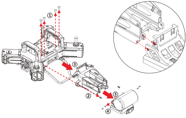
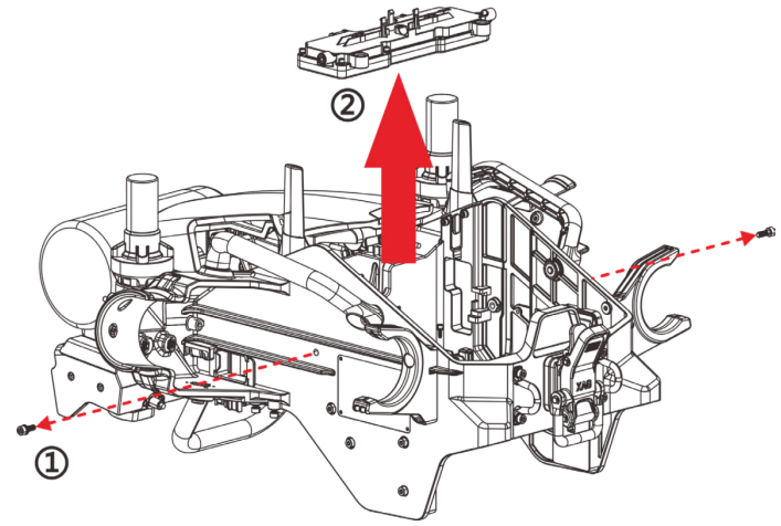
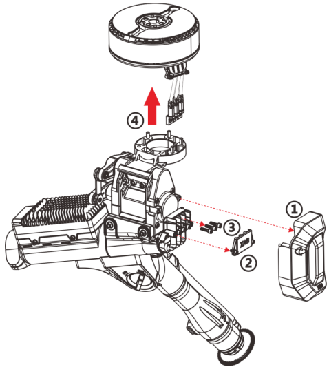
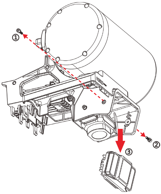
①② | M5*16 | 02-004-00939 | 29.0-31.0 kgf.cm |
④ | M4*12*8 | 02-004-00834 | 21-22 kgf.cm |
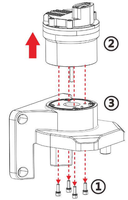
Disassembly Process
1. Disassemble the eight M5*16 fixing screws at the upper and lower connections between the fuselage and the head.
2. Remove the screws at the connection between the fuselage and both sides in front of the head.
3. Pull out and separate the head structure (the head and the sensing module structure can be completely separated).
4. Separate four M4*12*8 screws at the connection between the sensing module rack and the head.
5. Pull forward the separation sensing module.
Installation Process
1. Fix the machine head at the installation position of the body, and install the screws above, below and in front of the head.
2. Fix the sensing module bracket and the front of the head, and install the sensing module fixing screw.
Disassembly and Assembly Guide of P Series Tail frame
Screw Specifications and Installation Requirements
Serial Number | Screw Specification | Screw Number | Torque Requirements |
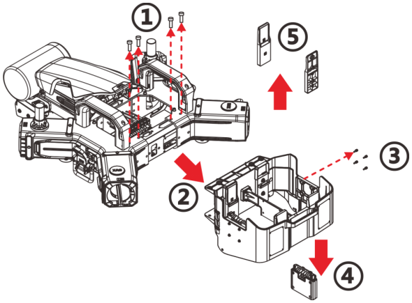
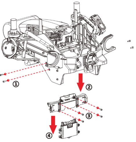
① | M5*16 | 02-004-00939 | 29.0-31.0 kgf.cm |
③ | M3*10*6 | 02-004-00624 | 6.5-7.5 kgf.cm |
⑤ | M4*12 | 02-004-00994 | 12.0-13.0 kgf.cm |
Disassembly Process
1. Remove eight M5*16 screws from the upper and lower connections between the fuselage and the tail frame.
2. Pull out the tail frame separation structure (the tail frame structure can be completely separated).
3. Separate the four M3*10*6 screws of the tail module.
4. Take out the tail plug module (make sure that the power cable has been separated before taking out).
5. Remove two M4*12 screws from the guide rail to separate the battery guide rail.
Installation Process
1. Fix the tail frame structure at the installation position of the fuselage and install the upper and lower screws of the tail frame structure.
2. Fix the tail plug module at the installation position of the tail frame, and install the fixing screws.
Disassembly and Assembly Guide of P Series Arm
Screw Specifications and Installation Requirements
Serial Number | Screw Specification | Screw Number | Torque Requirements |
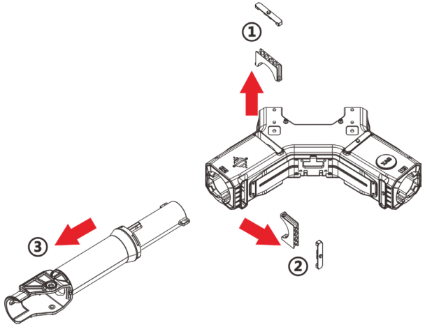
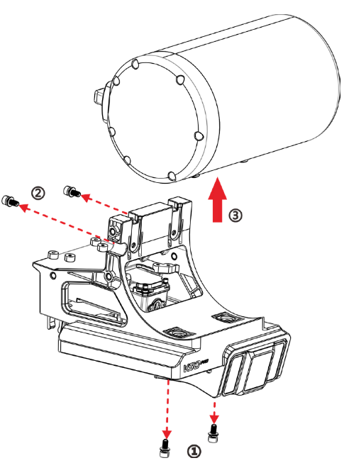
① ② | M5*32 | 02-004-00780 | 29.0-31.0 kgf.cm |
Disassembly Process
1. Disassemble the two M5*32 arm tube pressers above the fuselage.
2. Disassemble the two M5*32 arm tube pressing pieces on the side of the fuselage.
3. Pull out the separator arm (make sure that the cable of the arm is separated from the pipeline before removing the arm).
Precautions
• Disassemble method of the four arms of P100 and P100 Pro is same.
Installation Process
1. Install the arm and insert into the corresponding mounting hole.
2. Fasten the arm with the arm tube press.
3. Fasten the dustproof soft rubber lid.
Precautions
• It is necessary to avoid scratching and damage in assembly when cables and pipelines pass through the arm and the body. Wires and pipes shall be smoothed before final assembly.
Disassembly and Assembly Guide of P Series Main Body
Screw Specifications and Installation Requirements
Serial Number | Screw Specification | Screw Number | Torque Requirements |
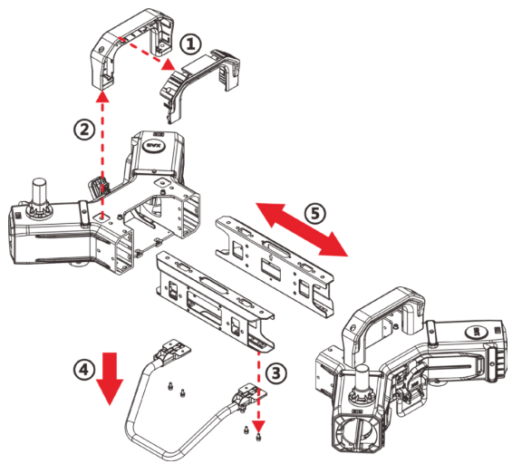
② | M6*22*12 | 02-004-01053 | 49.0-51.0 kgf.cm |
③ | M4*12*8 | 02-004-00834 | 12.0-14.0 kgf.cm |
⑤ | M5*16 | 02-004-00939 | 38.0 kgf.cm |
Disassembly Process
1. Disassemble four M6*22*12 screws in the handle on both sides of the main body and separate the handle.
2. Separate the handle and antenna link.
3. Remove six M4*12*8 screws below the support rod of the main body.
4. Detach the support rod.
5. Remove ten M5*16 screws fixing the side beam and cross beam of the main body, and separate the cross beam from the side beam.
Installation Process
1. Combine the side beam and the cross beam, and fix them with screws.
2. Install the support rod of the main body and fix with screws.
3. Install handle of the main body and fix with screws.
Disassembly and Assembly Guide of P Series Powertrain

Screw Specifications and Installation Requirements
Serial Number | Screw Specification | Screw Number | Torque Requirements |
① | ST2.9*8PB | 02-004-00942 | 4.5-5 kgf.cm |
② | ST4.2*8PB | 02-004-00918 | 6.5-7.5 kgf.cm |
③ (protective cover) | M3*10*6 | 02-004-00624 | 6.5-7.5 kgf.cm |
③ (ESC terminal) | M4*18 | 02-004-00978 | 25.0-26.0 kgf.cm |
③ (terminal holder) | ST4.0*16 | 02-004-00775 | 12.0-14.0 kgf.cm |
④ | M5*20 | 02-004-01130 | 38.0 kgf.cm |
⑥ | M5*16 | 02-004-00939 | 49.0 kgf.cm |
⑦ | M4*12*8 | 02-004-00834 | 12.0-14.0 kgf.cm |
Disassembly Process
1. Remove four ST2.9*8 PB screws on the decorative cover plate and separate the decorative cover plate from the anti-collision cotton.
2. Disassemble two ST4.2*8PB screws on the soft rubber support of the arm, and separate the soft rubber support of the arm.
3. Remove two M3*10*6 screws on the protective cover of the electrically adjustable terminal, three M4*18 screws on the fixed terminal and two ST4.0*16 screws on the terminal fixing base. Separate the protective cover, terminal and terminal holder.
4. Disassemble the four M5*20 screws on the motor base, and separate the motor base fixing screws, motor base damping rubber sleeve and motor base steel sleeve.
5. Push forward the motor base and motor to the end of the arm and lift up the separation motor base. Remove six M5*16 screws below the motor base to separate the power motor. (The power motor can be replaced and maintained after the above steps)
6. Remove the four M4*12*8 screws on the fixing lug of the electric regulator, and lift and separate the power electric regulator.
Installation Process
1. Lead out the power supply cable of power electric regulation to the connecting end of the arm and the fuselage.
2. Lead out the three-phase line cable of power electric regulation to the end of the machine arm and then fasten it with the electric regulation fixing screw.
3. Install the ESC terminal holder, and then install the power electric regulating three-phase cable to the ESC terminal holder.
4. Install the power motor on the motor base and fix it with the power motor screws.
5. Insert the motor base combined with the motor into the arm, and fix it with motor base damping rubber sleeve, motor base steel sleeve and screws.
6. Connect and fasten the three-phase cable of the power motor with the three-phase cable end on the fixed and electrically regulated terminal holder.
7. Install the protective cover of the electrically adjustable terminal and the soft rubber support of the machine arm.
8. Install the anti-collision cotton and decorative cover and fix them with screws.
V Series Disassembly and Assembly Procedure
Disassembly and Assembly Guide of V Series Hub board
Screw Specifications and Installation Requirements
Serial Number | Screw Specification | Screw Number | Torque Requirements |
① | M4*12*8 | 02-004-00834 | 10.0-11.0 kgf.cm |
Disassembly Process
1. Remove the two M4*12*8 screws on both sides of the hub board .
2. Pull back the hub board to withdraw from the preset position, and lift up and separate the hub board .
Installation Process
1. Push the hub board into the preset position from the rear.
2. Install the fixing screw of the wiring collecting board.
Precautions
•Install the hub board shall clamp in the reposition and fasten it with screws.
•Fasten the board before inserting cable.
• All cables in the connection shall be separated before disassembly.
Disassembly and Assembly Guide of V Series Tail Plug
Screw Specifications and Installation Requirements
Serial number | Screw specification | Screw number | Torque requirements |
① | M4*10*8 | 02-004-00833 | 10.0-12.0 kgf.cm |
③ | M4*10*8 | 02-004-00833 | 10.0-12.0 kgf.cm |
Disassembly Process
1. Disassemble four M4*12*8 fixing screws of the cross beam on both sides of the main frame (two screws on the left and two screws on the right).
2. Separate the beam and the tail group.
3. Disassemble the four M4*12*8 fixing screws of the tail plug.
4. Separate the tail plug and the beam.
(If there is a "corner device" to be removed, the third step to the fourth step can be carried out directly without removing the beam)
Installation Process
1. Assemble the tail plug and the cross member.
2. Install the assembled tail plug and edge beam assembly to the main frame.
(If the crossbeam is not disassembled, the tail plug can be directly assembled for fixation)
Disassembly and Assembly Guide of V Series Steering Gear
Screw Specifications and Installation Requirements
Serial Number | Screw Specification | Screw Number | Torque Requirements |
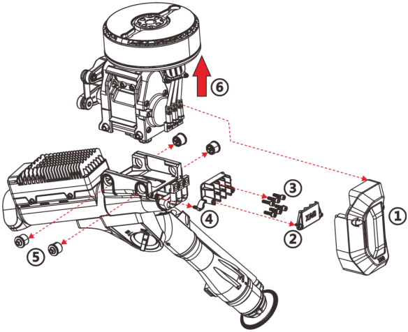
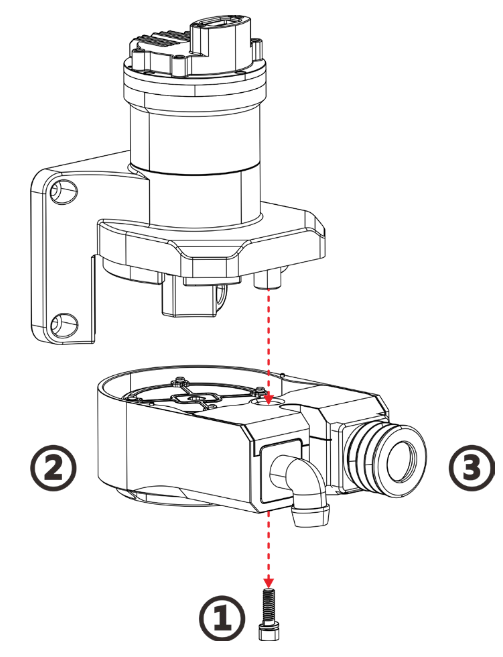
① | M4*10*8 | 02-004-00833 | 17.0-18.0 kgf.cm |
② (protective cover) | M3*8 | 02-004-00937 | 5.0-6.0 kgf.cm |
③ (ESC terminal) | M4*18 | 02-004-00978 | 25.0-26.0 kgf.cm |
④ (terminal holder) | ST4.0*13 | 02-04-01043 | 9.0-10.0 kgf.cm |
⑤ | M5*17 | 02-04-01039 | 25.0-27.0 kgf.cm |
Disassembly Process
1. Remove two M4*10*8 screws from the decorative cover of the arm, and separate the arm from the cover.
2. Remove two M3*8 screws on the terminal protection cover, and separate the terminal holder from the terminal protection cover.
3. Remove three M4*18 screws from the power motor and the three-phase cable for power electric regulation.
4. Remove two ST4.0*13 screws from the terminal holder, and separate the terminal fixing holder.
5. Disassemble four M5*17 screws, damping rubber sleeve and steel sleeve of the steering gear, and separate the fixing screws.
6. Move the steering gear horizontally to the end of the arm, and lift the steering gear out.
Installation Process
1. Install the power steering gear (including power motor) module assembly to the arm.
2. Install the fixing screws, damping rubber sleeve and steel sleeve of the steering gear, and fasten screws.
3. Install the terminal holder of the electric speed controller, then install the three-phase cab of the to the ESC terminal holder.
4. Connect and fasten the three-phase cable of the power ESC with the three-phase cable end on the fixed and electrically regulated terminal holder.
5. Install the protective cover of ESC terminal and the soft rubber support of the arm.
6. Install the arm trim cover.
Precautions
• Make sure that the power supply is disconnected before removing the power motor.
• Before installation, make sure that the contact surface of the terminal is no damage and dirt.
• When installing the power ESC, the cable shall be led out from the arm to the combination position first.
• Some part of cables need to be wrapped with acetic acid tape to avoid possible hard friction.
Disassembly and Assembly Guide of V Series Power Electric Tuning
Screw Specifications and Installation Requirements
Serial Number | Screw Specification | Screw Number | Torque Requirements |
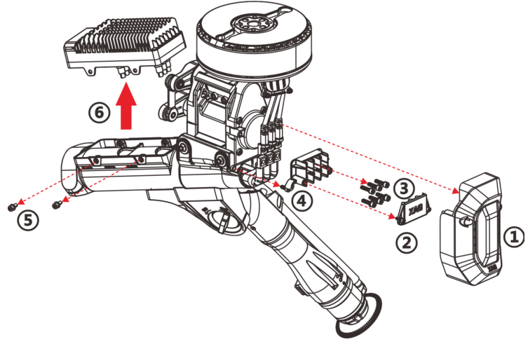
① | M4*10*8 | 2 | 17.0-18.0 kgf.cm |
② (protective cover) | M3*8 | 2 | 5.0-6.0 kgf.cm |
③ (ESC terminal) | M4*18 | 3 | 25.0-26.0 kgf.cm |
④ (terminal holder) | ST4.0*13 | 2 | 9.0-10.0 kgf.cm |
⑤ | M4*10*8 | 4 | 11.0-12.0 kgf.. cm |
Disassembly Process
1. Remove two M4*10*8 screws from the arm decorative cover and separate the arm from the cover.
2. Remove two M3*8 screws from the terminal protection cover, and separate the terminal holder from the terminal protection cover.
3. Remove three M4*18 screws from the power motor and the three-phase cable for power electric regulation.
4. Disassemble the two ST4.0*13 screws fixed on the terminal holder and separate the terminal fixing holder.
5. Disassemble the four M4*10*8 screws on the fixing lug of the ESC, and separate the fixing screws.
6. Extract that power ESC.
Installation Process
1. Install the power electric regulator to the arm.
2. Install the fixing screws, damping rubber sleeve and steel sleeve of the steering gear, and the fixing screws.
3. Install the ESC terminal holder, and then install the power electric regulating three-phase cable to the ESC terminal holder.
4. Connect and fasten the three-phase cable of the power motor with the three-phase cable end on the fixed and electrically regulated terminal holder.
5. Install the protective cover of the electrically adjustable terminal and the soft rubber support of the machine arm.
6. Install the arm decorative cover.
Precautions
• When installing the power ESC, the cable shall be led out from the arm to the combination position first.
• Some part of cables need to be wrapped with acetic acid tape to avoid possible hard friction.
• Before installation, make sure that the contact surface of the terminal is free from damage and dirt.
Disassembly and Assembly Guide of V Series Power Motor
Screw Specifications and Installation Requirements
Serial Number | Screw Specification | Screw Number | Torque Requirements |
① | M4*10*8 | 02-004-00833 | 17.0-18.0 kgf.cm |
② (protective cover) | M3*8 | 02-004-00937 | 5.0-6.0 kgf.cm |
③ (ESC terminal) | M4*18 | 02-004-00978 | 25.0-26.0 kgf.cm |
④ | M5*16 | 02-004-00939 | 25.0-27.0 kgf.cm |
Disassembly Process
1. Remove two M4*10*8 screws from the arm decorative cover and separate the arm from the cover.
2. Remove two M3*8 screws from the terminal protection cover, and separate the terminal holder from the terminal protection cover.
3. Remove three M4*18 screws from the power ESC and the three-phase cable for ESC.
4. Remove five M5*16 screws from the base of ESC, and lift the ESC for separation.
Installation Process
1. Assemble the ESC and the steering gear and fix them with screws.
2. Connect the three-phase wire of the ESC terminal and fix it with screws.
3. Assemble the ESC terminal protective cover and fix it with screws.
4. Assemble the decorative cover of the arm and fix it with screws.
Precautions
• Some part of cables need to be wrapped with acetic acid tape to avoid possible hard friction.
• Before installation, make sure that the contact surface of the terminal is no damage and dirt.
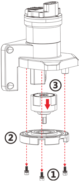
Disassembly And Assembly Guide Of V Series Steering Gear (Independent Model)
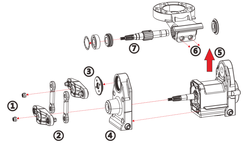
Disassembly Process
1. Disassemble and separate the fixing nut from the rudder arm.
2. Disassemble the rudder arm and the connecting rod of the steering gear (it can be disassembled as a whole, if it is intact and replaced).
3. Turn counterclockwise to remove steering gear shaft end gland.
4. Remove the fixing screws of the front cover of the steering gear, and separate the cover of the steering gear.
5. Take out the motor base, motor base spline, bearing, retaining ring and other accessories.
6. Remove the fixing screw of the spline in the motor base, and take out the spline power spindle after removal.
7. Spline bearing, soft rubber pad of steering gear cover and other accessories shall be separated if needed.
Precautions
• In step 1, the fixing nut of the rudder arm is embedded with anti-stripping glue, which cannot be reused after disassembly.
• In step 7, the rubber pad of the soft cover of the steering gear must be installed in place in order, otherwise the steering gear will not work.
• Pay attention to the centering state during the installation of the steering gear, and confirm that the steering gear has been centered before installing the rudder arm.
• The steering gear must be calibrated after the installation of the steering gear.
Disassembly and Assembly Procedure of Sensing System Module
Disassembly and Assembly Guide of Terrain Follow Module
Screw Specifications and Installation Requirements
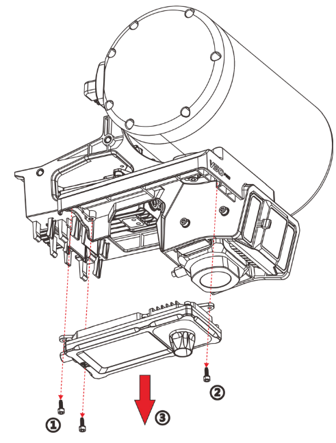
Serial Number | Screw Specification | Screw Number | Torque Requirements |
① | M2.5*8*4.5 | 02-04-00523 | 3.5-4 kgf.cm |
Disassembly Process
1. Disassemble the two M2.5*8*4.5 screws at the rear of the terrain follow module.
2. Disassemble one M2.5*8*4.5 screw in front of the terrain follow module.
3. Detach the terrain follow module downward.
Installation Process
1. Install the terrain follow module to the sensing system bracket.
2. Install and tighten the fixing screws of the terrain follow module.
3. Detach the terrain follow module downward.
Visual Disassembly Guide to Ground Camera
Screw Specifications and Installation Requirements
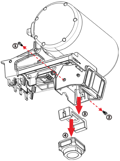
Serial Number | Screw Specification | Screw Number | Torque Requirements |
① | M3*10*6 | 02-004-00624 | 7-8 kgf.cm |
② | M2.5*8"4.5 | 02-04-00523 | 3.5-4 kgf.cm |
Preamble disassembly
1. Disassembly of terrain follow module.
Disassembly Process
1. Disassemble the M3*10*6 screw on the right side of the ground camera (it is required to disassemble and separate the terrain follow module first).
2. Remove the M3*10*6 screw on the left side of the ground camera.
3. Pull down to separate the ground camera holder and the ground camera.
4. Remove the M2.5*8”4.5 screw on the back of the ground camera holder and separate the camera from the holder.
Installation Process
1. Disassemble the screws of the fixed seat of the ground camera (need to disassemble and separate the terrain follow module first).
2. Remove the screws of the ground camera fixing base.
3. Pull down to separate the ground camera holder and the camera.
4. Remove the screws on the back of the ground camera holder and separate the camera from the holder.
Precautions
• Make sure that the left screw is not blocked and can be installed smoothly during installation.
Disassembly and Assembly Guide of Forward-Looking Visual Part
Screw Specifications and Installation Requirements
Serial Number | Screw Specification | Screw Number | Torque Requirements |
① | M3*8 | 02-004-00937 | 6-7 kgf.cm |
Preamble disassembly
1. Disassembly of terrain follow module.
Disassembly Process
1. Disassemble the M3*8 fixing screw on the left side of the front camera (it is required to disassemble and separate the terrain follow module first).
2. Remove the M3*8 screw on the right side of the front camera.
3. Pull down and detach the front camera.
Installation Process
1. The front camera is installed in the pre-position.
2. Fixing with screws.
Precautions
• Make sure that the left screw is not blocked and can be installed smoothly during installation.
Disassembly and Assembly Guide of Obstacle Avoidance Radar
Screw Specifications and Installation Requirements
Serial Number | Screw Specification | Screw Number | Torque Requirements |
① | M4*10*8 | 02-004-00833 | 11-12 kgf.cm |
Preamble Disassembly
1. Disassembly of terrain follow module.
2. Ground vision module removal.
Disassembly Process
1. Remove the fixing screws under the obstacle avoidance radar (it is required to disassemble and separate the terrain follow module and ground camera first).
2. Remove the fixing screws on the back of the terrain follow module.
3. Lift up and separate the terrain follow module.
Precautions
• Align the slot behind the radar during installation.
Disassembly and Assembly Procedure of Spraying System Module
Disassembly and Assembly Guide of Peristaltic Pump Synchronizing Disc
Screw Specifications and Installation Requirements
Serial number | Screw specification | Screw number | Torque requirements |
① | M4*40*8 | 02-004-00982 | 15.0-16.0 kgf.cm |
Disassembly Process
1. Remove one M4*40*8 fixing screw of the synchronizing disc.
2. Downward separate the peristaltic pump synchronizing disc module.
3. Separate the connector of the peristaltic pump tube in the synchronizing disc if needed.
Installation Process
1. Install the peristaltic pump connector module.
2. Engage the synchronizing disc module with the peristaltic pump deceleration group.
3. Install retaining screws of the synchronizing disc.
Disassembly and Assembly Guide of Planetary Gear of Peristaltic Pump
Screw Specifications and Installation Requirements
Serial number | Screw specification | Screw number | Torque requirements |
① | M4*10*8 | 02-004-00833 | 11-12 kgf.cm |
Disassembly Process
1. Disassemble the fixing screws of the lower cover of the reduction gearbox.
2. Separate the cover of the reduction gear downward.
3. Separate the planetary gear set.
Precautions
• If the planet gear needs to be removed, the peristaltic pump synchronizing disc should be removed first.
Installation Process
1. Install the planetary gear set (calibrate the meshing of each set of gears during installation).
2. Install the lower cover of the reduction gearbox and fix it with screws.
Precautions
• Before installation, check whether the planetary gear set has been installed in place, the gears operate smoothly, and the engagement is normal.
• When installing the lower cover, make sure that the seal ring is not missing or damaged.
Disassembly and Assembly Guide of Peristaltic Pump-motor Unit
Screw Specifications and Installation Requirements
Serial number | Screw specification | Screw number | Torque requirements |
① | M4*10*8 | 02-004-00833 | 11-12 kgf.cm |
Preamble disassembly
1. Peristaltic pump synchronizing disc module removal.
2. Peristaltic pump planetary gear removal.
Disassembly Process
1. Remove the fixing screw of the moter.
2. Detach peristaltic pump motor.
3. If needed: check the waterproof rubber ring, and repair or replace it if it is damaged.
Installation Process
1. Install the peristaltic pump motor (the motor shall be installed and fixed first, and then the planetary gear shall be installed during installation).
2. Use screws to fix the motor.
Precautions
• Make sure that the motor output shaft and the gear are intact before installation.
• Keep the occlusion between the motor output gear and the planetary gear to avoid blocking or sweeping teeth.
Disassembly and assembly procedures of Spreading System Module
Disassembly and Assembly Guide of Auger
Screw Specifications and Installation Requirements
Serial Number | Screw Specification | Screw Number | Torque Requirements |
① | M4*16*8 | 02-004-00836 | 12.5-13.5 kgf.cm |
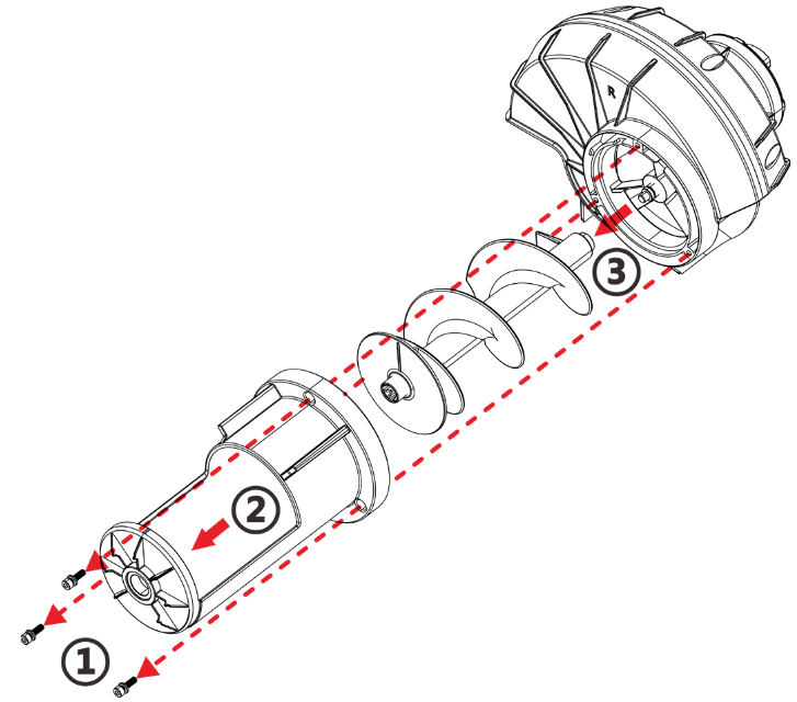
Disassembly Process
1. Disassemble two M4*16*8 fixing screws of Auger feeding round tube.
2. Separate the feeding round tube of Auger.
3. Separate the main body of Auger.
Installation Process
1. Assemble Auger feeding round tube and the Auger main body.
2. Use screws to fix the Auger feeding round tube.
Precautions
• Check whether the magnet on the main body of Auger is intact without falling off before installation.
• Calibrate the position of the magnet on the main body of Auger during installation.
Disassembly and Assembly Guide of Throwing Disc
Screw Specifications and Installation Requirements
Serial Number | Screw Specification | Screw Number | Torque Requirements |
① | M4*10*8 | 02-004-00833 | 10.0-11.0 kgf.cm |
③ | M4*10*8 | 02-004-00833 | 10.0-11.0 kgf.cm |
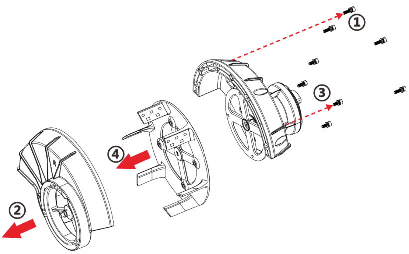
Disassembly Process
1. Disassemble the four M4*10*8 screws of the throwing disc motor mounting part.
2. Separate the motor mount from the throwing disc motor mounting part.
3. Remove four M4*10*8 screws from the throwing disc and the flange disc.
4. Detach the throwing disc.
Installation Process
1. Install the throwing disc to the flange disc and fix it with screws.
2. Assemble the throwing disc mounting part with the motor mounting and fix with screws.
Disassembly and Assembly Guide of Throwing Disc Motor
Screw Specifications and Installation Requirements
Serial Number | Screw Specification | Screw Number | Torque Requirements |
① | M4*8 | 02-04-01031 | 6.0-7.0 kgf.cm |
③ | M4*10*8 | 02-004-00833 | 10.0-11.0 kgf.cm |
Disassembly Process
1. Disassembly of throwing disc.
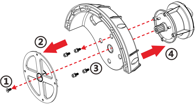
Disassembly Process
1. Remove one M4*8 screw from the flange disc.
2. Separate the flange disc.
3. Disassemble the four M4*10*8 screws of the throwing disc motor.
4. Detach the throwing disc motor.
Precautions
•Ensure the engagement between the alignment flange disc and the gear of the throwing disc motor during installation.
Installation Process
1. Install the throwing disc motor and fix it with screws.
2. Install the flange disc and fix it with screws.