Chapter 12: Portable RTK station (XRTK4)
Portable RTK station (XRTK4)
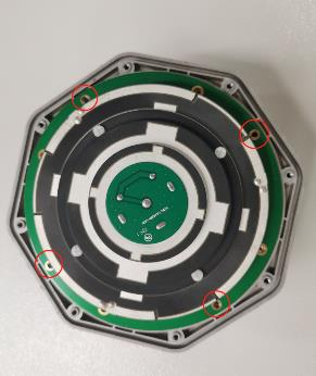
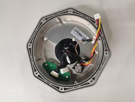
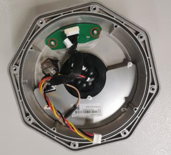
Hardware
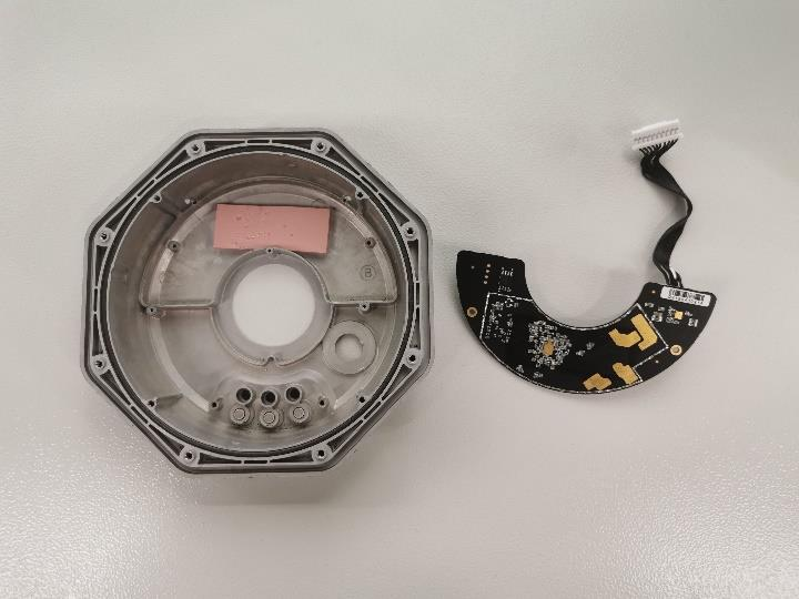
GNSS Antenna
The GNSS antenna is a precision tuned, stacked patch GNSS antenna that provides reliable and consistent positioning services across the full bandwidth of the antenna. Its superior positioning accuracy and powerful system compatibility makes it ideal to be integrated into various surveying and RTK applications.
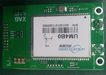
RTK board
RTK board is all-constellation all-frequency RTK positioning module based on the high-performance high-precision SoC - NebulasII, which is developed by Unicore Communications. It supports multiple satellite signals, including BDS B1I/B2I/B3I/B1C/B2a, GPS L1/L2/L5, GLONASS L1/L2, Galileo E1/E5a/E5b and QZSS L1/L2/L5. It has adopted narrowband anti-jamming technology.
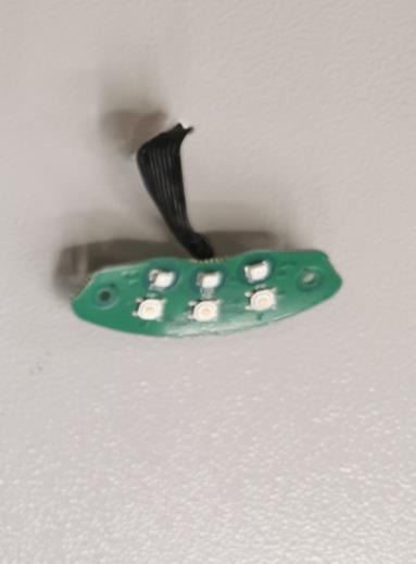
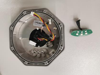
Button board
Button board allows user to press F1/F2/F3.
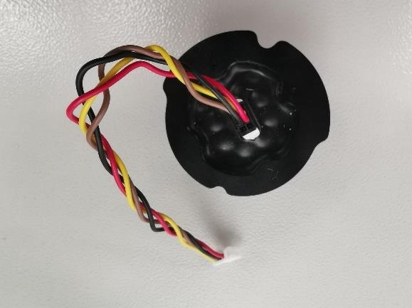
WIFI board
WIFI board is the printed circuit board (PCB) that Wi-Fi enabled system on chip (SoC) module developed by XAG, with full TCP/IP stack microcontroller capability
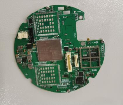
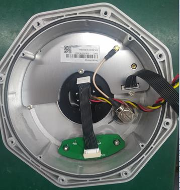
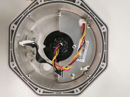
Main board
Main board it the main printed circuit board (PCB) in general-purpose computing. It creates the union between various components, like CPU, RAM, Memory slots, button board and other various component so that it aims at RTK performance. It plays a vital role in data switched from one component to another, including processing network, RTK, WIFI data, etc.
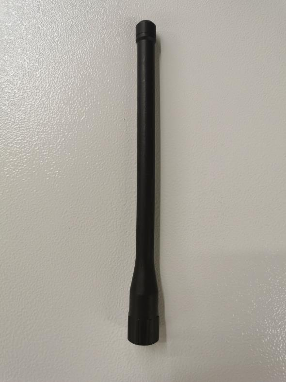
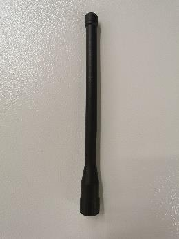
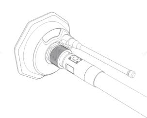
Rod antenna
Rod antenna is for WIFI use, with the radio frequency of 2.4/5.8GHz. It converts electrical signals into
electromagnetic waves and radiates them. Also, it converts electromagnetic waves from received beam
into electrical signals
Other maintenance parts
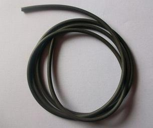
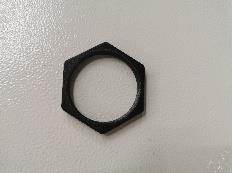
1. 02-001-00569, seal rubber ring
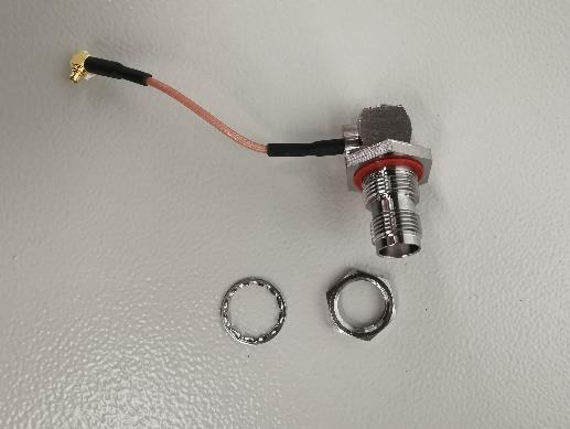
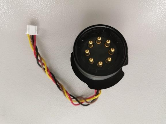
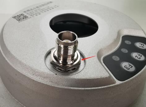
2. 01-027-00803, RF connector

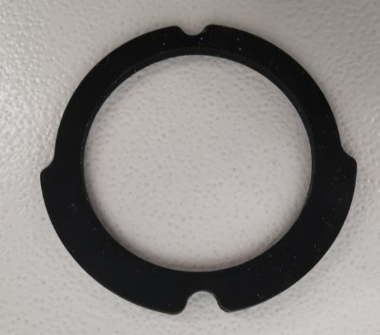
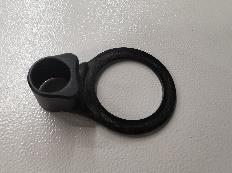
3. 02-001-03239, Fixture column waterproof gasket
4. 02-025-00079, Button film
5. Fixture column
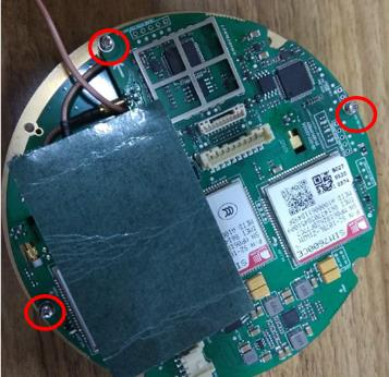
Disassembly
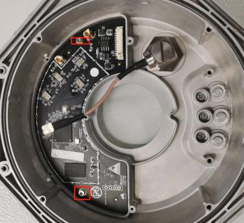
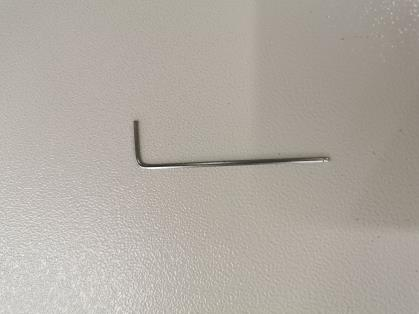
1. Use large adjustable wrench to unscrew the hexagon nut, take out the platen

2. Unscrew counterclockwise to remove rob antenna
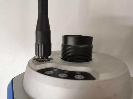
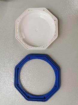
3. Remove upper case and rubber seal ring (blue)
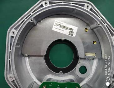
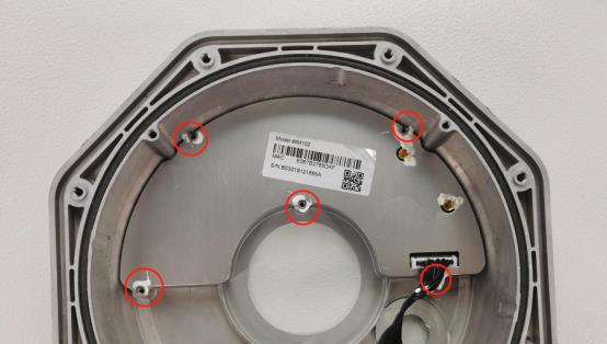
4. Remove the circuitry from bottom shell, unscrew 4 screws
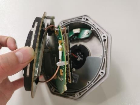
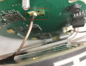
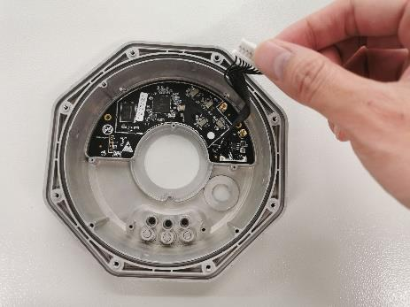
5. Unplug flexible flat cable and RF connector pins
Please be aware of the aligning hole.
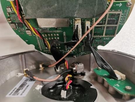
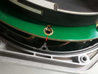
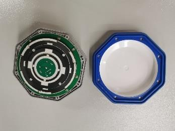
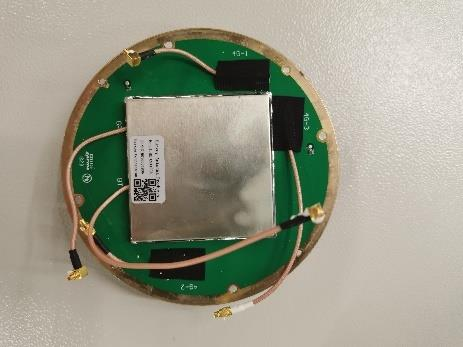
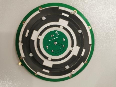
6. Remove GNSS antenna, unscrew 3 screws, unplug RF connector pin
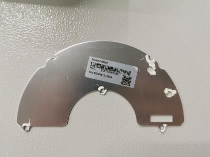
the bottom and upper view of GNSS antenna
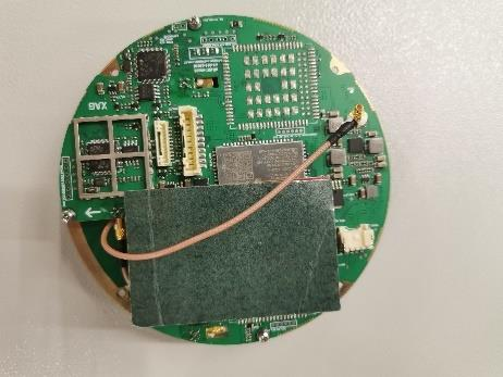
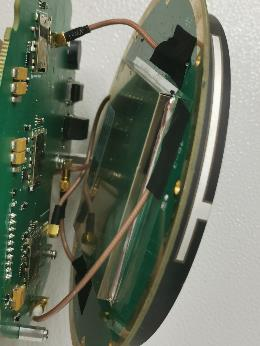
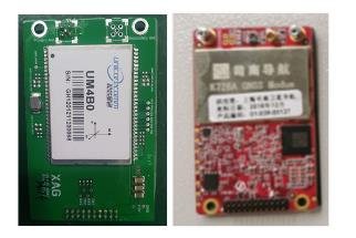
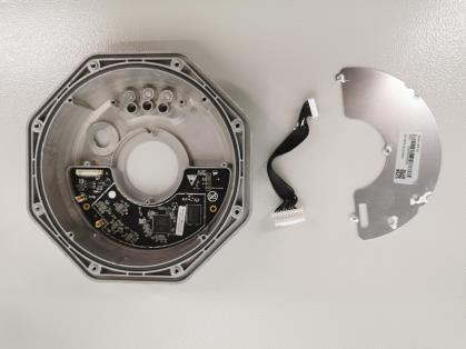
The bottom and upper view of main board with RTK module
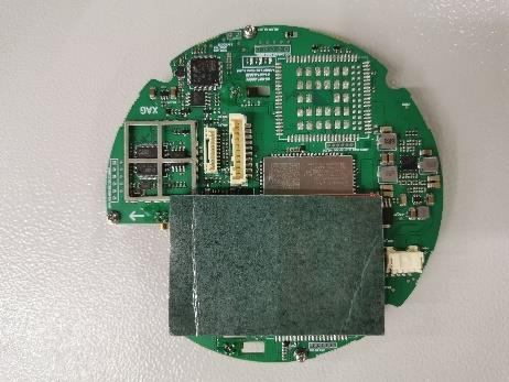

7. Separate RTK board and main board, unscrew 2 screws
RTK board
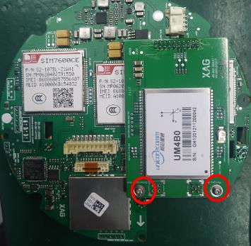
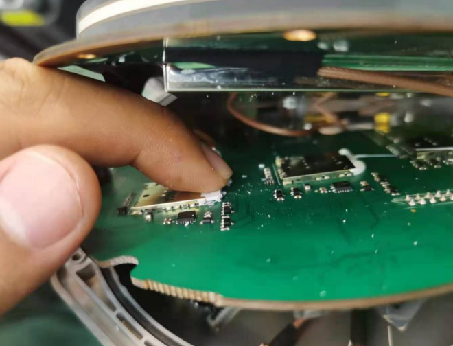
8. Remove sim card(s)
9. Remove button board, unscrew 2 screws
10. Remove RF connector, use wrench to unscrew the hexagon nut

11. Remove GNSS fixture column and its gasket
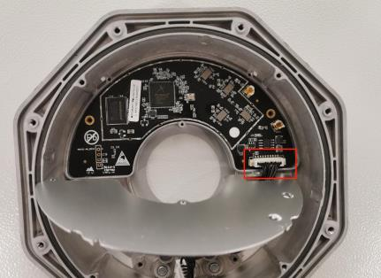
12. Remove EMI shield, unscrew 5 screws
Remove FFC
The view of EMI shield
13. Remove WIFI board, unscrew 2 screws
Note: The thermal conductive silicone pad pastes between the WIFI board and the bottom shield. It makes the WIFI board difficult to be removed from the bottom shell. In this case, we can use a heater to warm up the bottom shell for 1-~15 minutes. Then plug on the cable, grab the cable, and slowly pill the WIFI board away from the bottom shell
Explosive and Spare Part
The part list contains the exploded view of the RTK mushroom head as well as the associated part number.
Due to the 4G compatibility, there are three versions of RTK mushroom head, including Chinese version (CN), English version (EN), and Japanese version (JP).
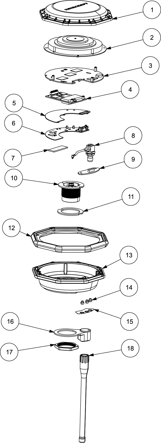
| No. | Part name |
(CN) 09-010- 00034 |
(EN) 09-010- 00037 |
(JP) 09-001- 00013 |
Flexible Flat cable | Screw | Screw Qty |
| 1 | RTK upper shell | 02-001-03238 | 02-001-03238 | 02-001-03238 | 02-004-00224 | 8 | |
|
2 |
GNSS Antenna |
01-003-00179 |
01-003-00179 |
01-003-00179 |
02-002-00999 02-004-00372 02-004-00418 |
3 3 4 |
|
| 3 | mainboard | 05-001-01682 | 05-001-01587 | 05-001-01666 | 02-004-00372 | 3 | |
| 4 | RTK board | 05-001-00547 | 05-001-00547 | 05-001-00547 | 02-004-00372 | 2 | |
|
5 |
EMI Shielding |
02-002-04744 |
02-002-04744 |
02-002-04744 |
02-004-00418 |
3 |
|
| 6 | WIFI board | 01-036-00144 | 01-036-00144 | 01-036-00144 | 01-027-01006 | 02-004-00161 | 2 |
|
7 |
Thermal Conductive Silicone Pad |
04-015-00119 |
04-015-00119 |
04-015-00119 |
|||
| 8 | RF connector | 01-027-00803 | 01-027-00803 | 01-027-00803 | |||
| 9 | Button board | 05-001-00246 | 05-001-00246 | 05-001-00246 | 01-027-00278 | 02-004-00418 | 2 |
| 10 | Fixture column | (申请保障料) | (申请保障料) | (申请保障料) | 01-027-00826 | ||
|
11 |
Fixture column waterproof gasket |
02-001-03239 |
02-001-03239 |
02-001-0323x 9 |
|||
| 12 | shell seal ring | 02-001-02349 | 02-001-02349 | 02-001-02349 | |||
| 13 | RTK bottom shell | 02-002-08628 | 02-002-08629 | 02-002-08629 | |||
| 14 | cylinder button | 02-002-02169 | 02-002-02169 | 02-002-02169 | |||
| 15 | Button film | 02-025-00079 | 02-025-00079 | 02-025-00079 | |||
| 16 | platen | 02-002-01926 | 02-002-01926 | 02-002-01926 | |||
| 17 | Hexagon nut | 02-002-01790 | 02-002-01790 | 02-002-01790 | |||
|
18 |
Rod Antenna |
01-003-00183 |
01-003-00183 |
01-003-00183 |
Troubleshooting
Scenario
| Scenario | Causes | Possible Solution |
| Fail to turn on |
Main board Fixture column Flexible Flat cable |
Replace Replace Replace |
| Fail to pair |
WIFI board Rob antenna RF connector Button board |
Replace Replace Replace Replace |
| RTK loss |
RTK board GNSS antenna Main board |
Replace Replace Replace |
| Network loss |
SIM card
Mainboard |
Replace or change another network provider Replace |
Awareness
- Grab your mushroom head properly. Never grab the rob antenna and move back and forth, which will result in the break of wire inside rob antenna
- Don’t stick the rover (mushroom head and rod) hard into the ground. The force may break the circuitry inside mushroom head.
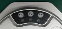
Check RTK Light indicators
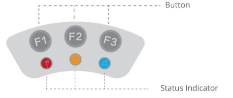
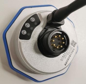
| LED INDICATOR | ICON | Button | ILLUSTRATION | IMPLICATION |
|
Wireless Communication Indicator 无线通信信号灯 |
|
F1 |
whether HDLS module can transmit and process data |
Solid Red :OK Flash Red (slow) : Initializing WLAN Flash Red (rapid): Low battery |
|
Cloud Communication Indicator 云通讯信号灯 |
|
F2 |
whether device can communicate with remote server (cloud or local network terminal) |
Flash Yellow (single): not connected Flash Yellow (double) : cloud server connected Flash Yellow (triple): LNT connected |
| RTK Indicator RTK 信号灯 |
|
F3 | related to RTK positioning |
Blue Light Off: None Blue Light: RTK Blue Single Flash: Single Blue Double Flash: Float Blue Triple Flash: Fix |


|
|
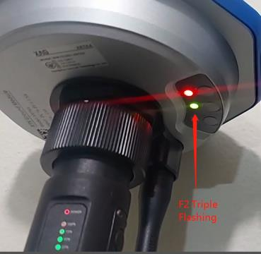 |
 When using LNT networking mode, please make sure the XRTK4 has F2 triple flashing
Apply XAG App account Privilege for LNT networking mode
If you are going to use LNT networking mode and want to pair your RTK station with LNT. You must download and install the XLINK firmware to your RTK station using XAG Agri 2 App and ACS2 2020 remote controller.
Before firmware update, please be aware of that the app account must have LNT privilege to view and download the LNT relevant firmware. If your account is not able to update to the LNT relevant firmware, your account possibly doesn’t have the LNT privilege. To solve this, please contact XAG technician for help. Provide your account ID when applying for privilege.
Check if XRTK4 has 4G SIM card inserted
All the RTK mushroom head has 4G Sim card inserted before shipment. Please do not remove 4G SIM card otherwise may cause the following issues:
- the RTK mushroom head may consistently stay offline during use.
- After credentials setting in RTK/LNT configuration, RTK will not connect to LNT, which means the RTK will not have triple light flashing.
4G SIM card can be replaced by local SIM if the RTK station is used under 4G networking mode.
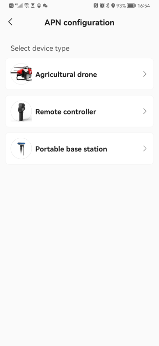
XRTK4 APN Setting (4G Network)
If XRTK4 is compatible with your local Telcom operator while it still can’t access internet with 4G SIM card inserted, then you may need to modify APN setting.
|
Step 1 Open XAG One App, go to Device |
 |
|
Step 2 Go to APN configuration |
 |
|
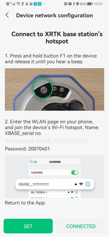
Step 3 Connect your smartphone to XRTK4 hotspot, and press CONNECTED |
 |
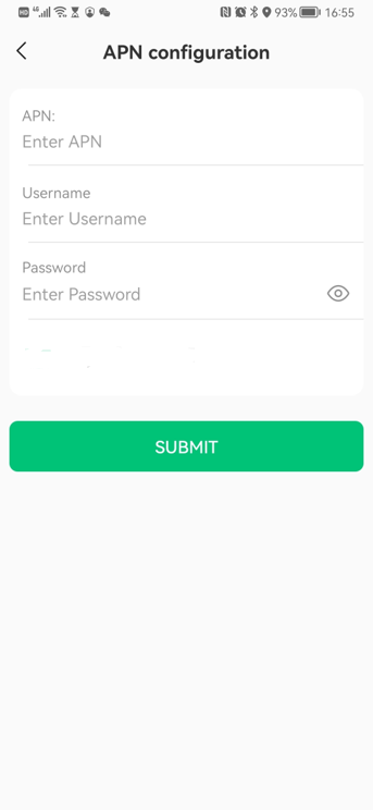
| Step 4 Input APN, Username, and Password. Press SUBMIT If you don't know the APN configuration information, please contact your local Telcom operator. |
 |
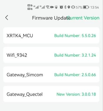
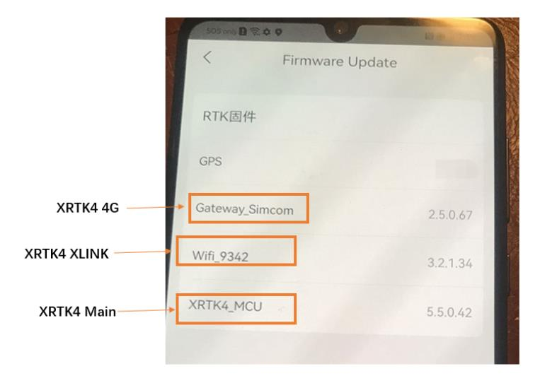
Check RTK firmware version before LNT networking mode configuration
Please make sure the RTK firmware satisfies the minimum requirement of LNT network configuration. If not, please update RTK firmware before configuration.
| Module | Description |
Firmware version (minimum requirement of LNT network configuration.) |
| XRTK4 Main | Related to mainboard | V5.5.0.33 |
| XRTK4 XLINK | Related to WIFI | V3.2.1.30 |
| XRTK4 4G | Related to 4G | V2.5.0.67 |
RTK firmware version using XAG One App
Device information using XAG Agri 2 App
Optional: Revert XRTK4 to adapt again with XP2020
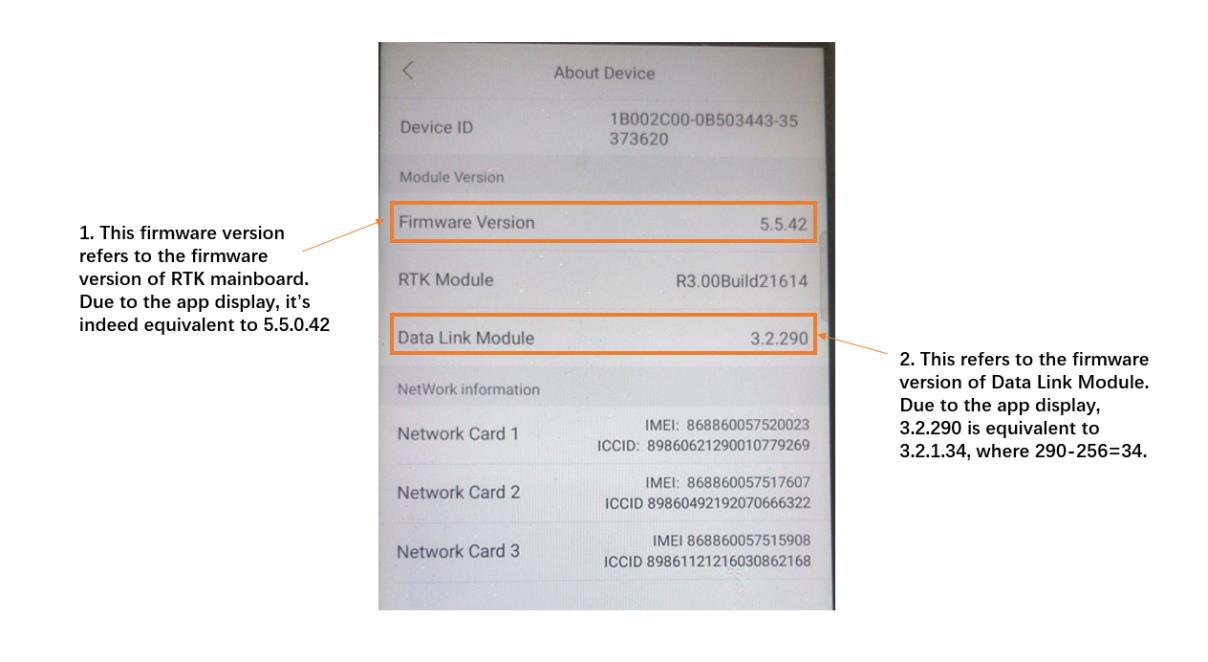
To revert XRTK4 to work again with XP2020, please check XRTK4 Data Link Module (XLINK) and do firmware downgrade if necessary.
Check Data Link Module
After the Data Link Module of XRTK4 station is upgraded to the version 3.2.XXX,
the XRTK4 station may encounter the issue as below:
- fail to use with XP2020.
- take a long time to go into FIX mode.
- UAVs (V40/P40/P100) or ACS2 2021 remote control fails to connect RTK or receive RTCM data.
The above issues may be due to the model of RTK module.
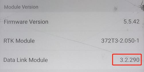
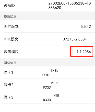
If your RTK module is 372T3-2.050-1, your XRTK4 station is the old model. The above issue may occur.
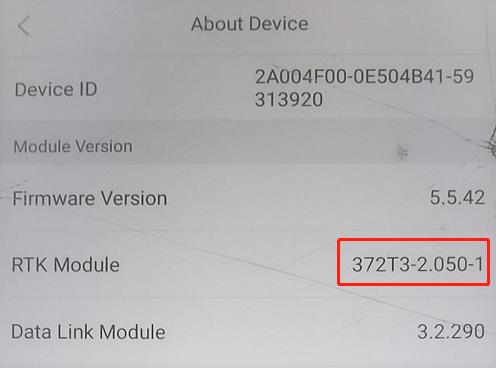
if your RTK module is R3.00Build21614, your XRTK station is the new model. The above issue will not occur.
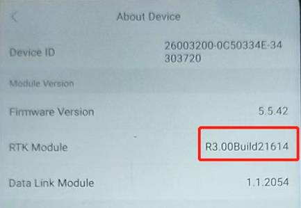
It’s highly recommended to use RTK module R3.00Build21614 in LNT network configuration.
XRTK4 Data Link Module Firmware Downgrade
If you are using the old RTK module 372T3-2.050-1 and having the above issues, you can revert the XRTK4 Data Link Module back to 1.1.XXXX, also called firmware downgrade from 3.2.XXX to 1.1.XXXX.
Preparation
- laptop, windows 10
- 2-hdls_fwupdate.exe (software to install XRTK4 firmware)
- xlinkhs_V1.1.2054_20220920.fw (XLINK Firmware)
- XRTK4 station (Data Link Module version 3.2.XXX)
Procedure
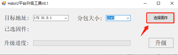
- on XRTK4 station, long press F1 to enable the XRTK4 WIFI
- connect laptop to XRTK4 hotspot
- open 2-hdls_fwupdate.exe and input parameters (172.31.0.1 and 2048)
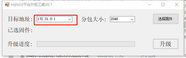
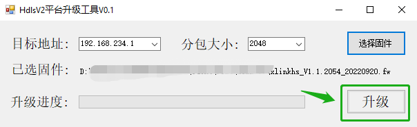
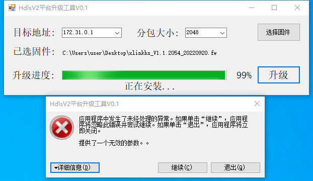
4. Choose firmware, xlinkhs_V1.1.2054_20220920.fw
5. update XLINK firmware
6. The tool will stop at 99% as the XRTK4 is restarting its WIFI module. Please ignore the warning. Wait for approximately 5 minutes.
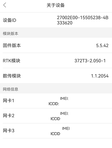
7. Use remote controller (ACB1 or ACS2 2020) and XAG Agri 2 App to check XRTK4 station firmware version
8. Test XRTK4 station with XP2020 or P30
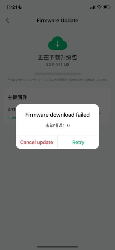
XRTK4 Portable Station Firmware update
XRTK4 portable station firmware update can only use below method:
- Mesh network: ACS2 2020, XAG Agri 2 App
- LNT network, Add XRTK to LNT, update XRTK on XAG One App
If the XRTK4 DATA Link module is above 3.XX.XXXX, its WIFI XLINK firmware can be updated locally without internet access. you can find it in the chapter of “firmware update”.
XRTK4 portable station CANNOT be updated under 4G networking mode (insert 4G SIM card inside XRTK4 module). The future version of APP will disable the firmware update interface of XRTK4 as its hardware does not support this feature.
The below example is that users fail to update XRTK4 firmware.
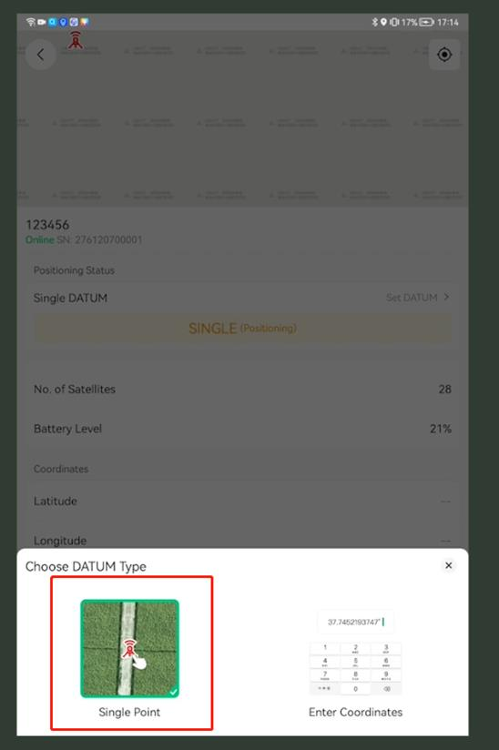
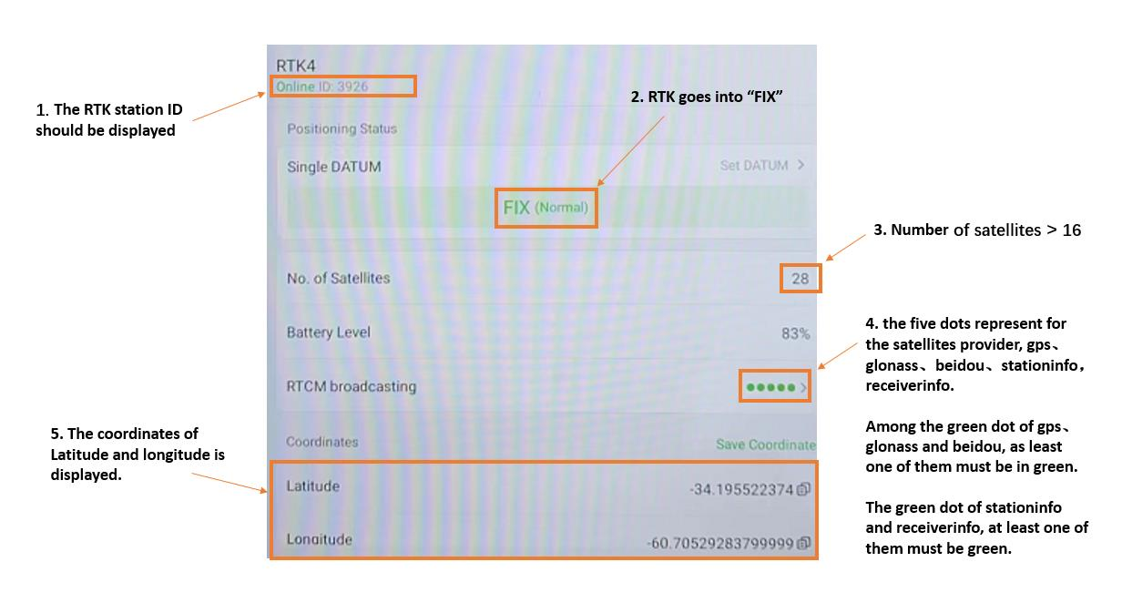
Signal point debug
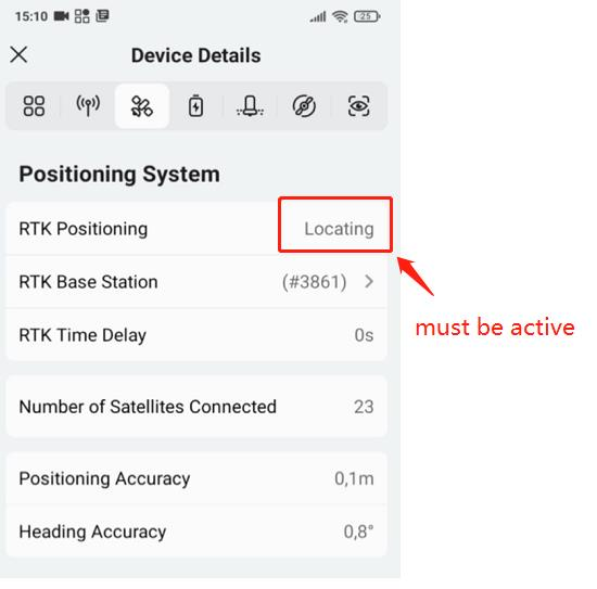
When using signal point positioning, please check the followings.
If you are not sure, please send the XAG technician the screen recording. The screen recording video should last for 5 minutes.
Check if UAV has RTK active
| UAV-RTK status | Photo |
| Connected | 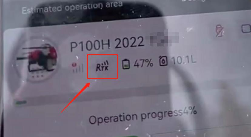 |
| Not Connected | 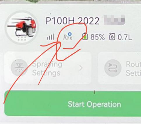 |
XRTK4 Factory Reset
To factory reset XRTK4, please press and hold the F2 and F3 button until you hear a long beep sound.

Fixed RTK Station
Overview
Insert SIM card into Mushroom head
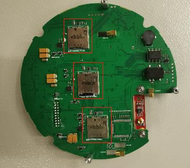
Remove the module and find the three SIM card slot

Slowly clean the white glue of the card slot with plastic tweezers
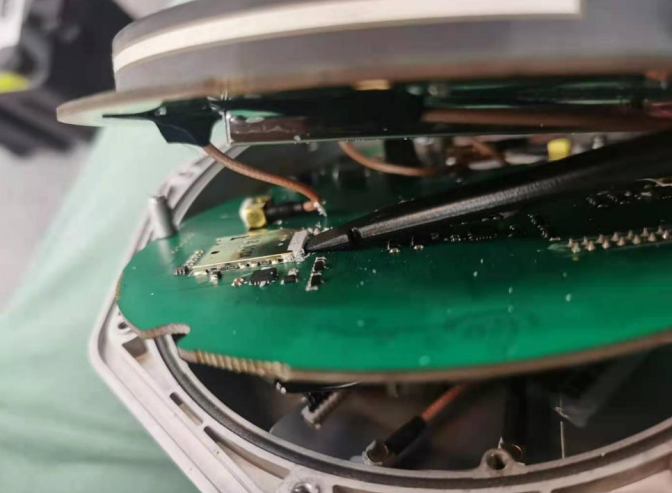
move the SIM card (with care and patience), insert your SIM card into the slot and close the head cover
again
Install Base Station
Site Selection
To ensure the normal operation of the base station, site selection should be guided by the following
principles:

① There should be no obstructions creating a shielding angle of over 15° around the level surface of the base station.
② Keep a minimum of 100m distance from the objects that are likely to produce multipath effect, including trees, water bodies, beaches, waterlogged areas and metals.
③ Keep a minimum of 100m distance from areas generating electromagnetic interference, such as microwave stations, radio towers, areas along the high-speed railway. The selected site should also be far from areas subject to vibration like those along the railway and highway.
④ See that the 4G signal is normal, and no tall buildings, obstructions of the satellite signal, will be built around the base station.
⑤ Make sure that no radio stations like microwave stations will be built around the base station in the future. The selected site should be far from areas with fragile geological structures, fault fracture zones and places being prone to landslide, settlement other local deformations, such as mining areas, oil and gas fields, groundwater funnel settlement areas, etc. In addition, flood-prone areas or places with great variation in water level should also be avoided.
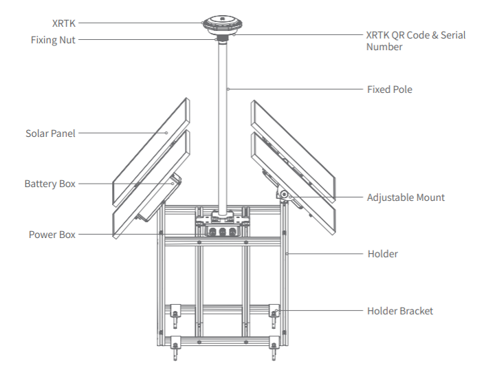
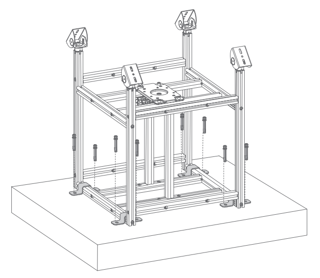
Install Fixed Base Station Holder
When installing the holder for the fixed base station, ensure that the adjustable mount of the solar panel is facing 5 to 10 degrees clockwise from due south, and there is no obstruction.
1. Drill and Install Directly
If the conditions are right, you may install directly the four brackets wherever possible on the ground by drilling holes for eight expansion bolts and secure the holder. This is the easiest as well as time- and cost-effective way to install the holder.
2. Build a Platform Before Installation
Build a concrete platform with dimensions of 1 x 1 x 0.15 m. Make sure the four brackets are properly installed on the platform after it hardens. Drill holes for the eight expansion bolts and secure the holder.
Keep the holder level as the bottom of it is anchored to the ground. Be careful with the drill and avoid causing damage to the brackets.
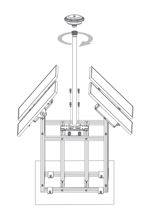
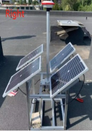
Install Solar Panels
Refer to the figure below and make sure the four solar panels are aligned with the screw holes on the adjustable mounts. Tighten the screws (two screws per panel) with a screwdriver. When this is done, adjust the angle of the solar panels to 45 degrees.

Install XRTK
1. Make sure the fixed pole is erected vertically and its bottom is in line with the reserved hole on the holder. Tighten the four screws with a screwdriver.
2. Insert the XRTK slot into the top of the fixed pole, and tighten the fixing nut by rotating it counterclockwise.
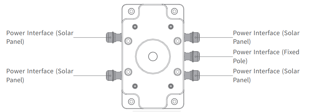
Wiring Quick Guide
Refer to the power wiring guide below and connect the 4pin power cables of the four battery boxes to the
holder's power box respectively. After this, connect the power cable of the fixed pole to the power box.
Online Application
Base Station Erection Information | |
Company |
|
Contact person |
|
Phone number |
|
Address |
|
Station Name |
|
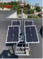
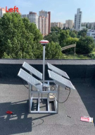
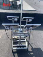
QR code photo, close shot photo, distant view photo | |
4 Photos of surrounding environment (Front, Rear, Left, Right) |
Below is the online application example:
Base station erection information(example) |
Company:XAG |
Contact person:Weichi |
Phone number: +8612345678 |
Address: XSpace, 115 Gaopu Rd, Guangzhou, P.R.C |
Station name: CN GUANGZHOU 123(Country+City+Number) |
QR code photo, close shot photo, distant view photo
|
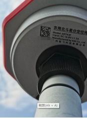
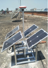
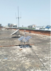
Photo of sorrounding environment
|
Once the application approved, your fixed station will be activated from XAG backend.
CORS – Provided by third party
Introduction
About Continuously Operating Reference Stations (CORS) Network
A Continuously Operating Reference Station (CORS) network is a network of RTK base stations that broadcast corrections, usually over an Internet connection.
The CORS network is a multi-purpose, multi-agency cooperative endeavor, combining the efforts of hundreds of government, academic, and private organizations.
The stations are independently owned and operated.
Each agency shares their GNSS/GPS carrier phase and code range measurements and station metadata with NGS, which are analyzed and distributed free of charge.
Application
The idea behind is to provide a common positioning platform in defined accuracy for the survey, mapping and monitoring of large infrastructure projects – as irrigation, railroad, canals, dams, smart cities, drainage planning along with management of revenue maps and state boundary management.
Reference: CORS Network (kerala.gov.in)
Configure CORS on App
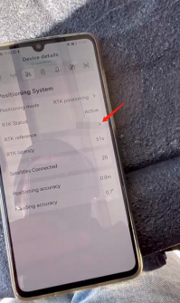
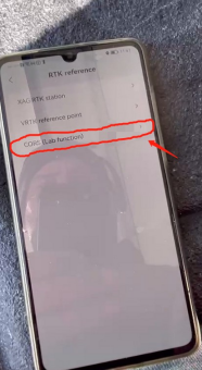
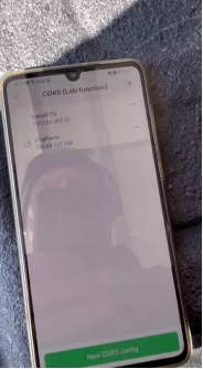
On the App, go to “device details”, “Positioning system”, “RTK reference”, CORS, choose the wanted CORS or create a new one.
CORS only support RTCM32 MSM4 protocol.