.png?height=120&name=Pegasus%20Robotics%20Logo%20-%20Portait%20(2).png)
Basic Intro of B13960S Battery

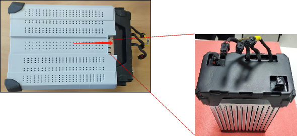
Model: B13960S Standard configuration: V40 / P100 / P40 agricultural UAV; advantage: The smart battery contains 13 high-capacity lithium polymer batteries and integrates BMS modules, It can monitor voltage, current, temperature and other status information in real time, and has charging protection function at the same time. During the use of the battery, it can feed back information to the load in real time. When the power is insufficient or fails, the BMS system will actively send an emergency stop command to ensure the power safety of the load.
B13960S use and daily maintenance
1. On-off operation mode of B13960S

Startup mode (2 long presses): In the shutdown state, connect the load and press the power button for at least 1 second, Wait for all power lights to flash at the same time, release the key at this time, Press and hold the key for at least 1 second until the battery beeps and the status indicator lights up
Shutdown mode (2 long presses): In the power on state, long press the power button for at least 1 second, Wait for all power lights to flash at the same time, release the key at this time, Press and hold the key for at least 1 second until the battery beeps and the status indicator goes out
2. Description of 2021 smart battery status indicator


B13960S status indicator: overcurrent lock and cell identity authentication technology are added. Cell identity authentication means that the battery cannot be used if the cell or mainboard is replaced and is not activated through background authentication.
3. Use and daily maintenance of 2021 smart battery
1. During use, do not plug and unplug the battery when the battery is turned on, otherwise the plug interface will ignite and damage the battery plug;
2. Before flight, please check whether the firmware version of the battery is the latest state on the app. If there is a new version, please update it before operation. Each firmware update is to modify some known problems, so be sure to update it;
3. Please handle the battery with care during use. Do not disassemble it without permission and repair it by yourself;
4. The battery is inflammable and explosive. Please do not sit on the battery, carry heavy objects above the battery or put pressure on the battery;
5. During operation, please try to keep more than 2 power lamps (i.e. 30%) for return charging to avoid over discharge of the battery;
6. During operation, the battery temperature exceeds 60 ℃ for continuous operation. Continuous high-temperature operation will shorten the service life of the battery, and in serious cases, it will lead to smoke, explosion, etc;
7. Please keep away from inflammables, explosives or gases when charging;
8. Do not use this battery to supply power to other equipment.
9. The storage and use ambient temperature of the battery is between 10 ℃ and 30 ℃;
10. The battery shall not be stored in a humid environment, otherwise it will cause corrosion or oxidation of the circuit board in the battery and cause bad performance;
11. Check the battery plug regularly during daily use. If any blockage is found, please take it out with insulating tools;
12. If liquid is found on the battery during use, please clean it with a dry cloth in time to avoid immersion in the battery and damage the battery circuit board;
13. After each Sorty operation, the battery shall be charged in time to avoid over discharge caused by low-power storage;
14. Please use the standard charger provided by XAG for charging. The customer shall be responsible for battery accidents, flight faults and other problems caused by charging with a charger not provided by XAG;
15. If it needs to be stored for a long time, the battery needs to be charged and discharged every 90 days to maintain the activity of the battery.
4. Emergency treatment of B13960S
Emergency handling principles:
1. Ensure the safety of personnel;
2. Timely take photos to obtain evidence and report to relevant personnel;
3. Quickly take the following effective measures
Scenario 1: Only temperature is high, but no fire
Measures: in case of smoke, turn off the power supply in time,let it cool naturally. During the cooling process, please observe whether the heating of the battery is relieved. If not, please put the battery in clean water for cooling;
Scenario 2:Battery smoking
Measures: take out the battery in time and put it in clean water for cooling (soaking)
Scenario 3: The battery suddenly smokes during charging
Measures: if the battery suddenly smokes during charging, please cut off the main power supply of the charger immediately and remove the battery on the premise of ensuring the safety of personnel. If personnel cannot get close to the battery, please abandon the equipment and directly use clean water jet or fire extinguisher to cool down and extinguish the fire;
Scenario 4: The drone crashed in flight, resulting in battery smoke
Measures: take out the battery on the premise of ensuring the safety of personnel. If personnel cannot get close to it, please abandon the equipment and directly use clean water jet or fire extinguisher to cool down and extinguish the fire. When it is determined that the battery temperature has decreased and there is no danger, proceed to the next step.
Battery disassembly process and precautions
Battery disassembly process
Step 1: Remove the battery head case
| Step 1: Remove the 4 anti-collision rubber pads above the smart battery |  |
| Step 2: Remove 4 screws from the upper shell of the smart battery |  |
Step 2: Remove the connecting wire
|
Step 1: remove two screws at the positive and negative poles of the power copper bar
|
 |
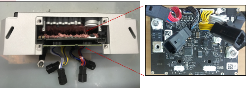
Step 2: Remove 2 cell sensor wires, 1 temperature sensor wire and 1 signal wire connecting the battery cell and BMS intelligent battery management system  When removing the core detection line, the sequence is red line(6-13S) → black line(1-5S) → yellow line(NTC temperature detection and encrypted communication) When removing the core detection line, the sequence is red line(6-13S) → black line(1-5S) → yellow line(NTC temperature detection and encrypted communication) |
 |
Step 3: Remove the battery plug assembly
| Step 1: remove the 4 screws on the battery plug female holder | 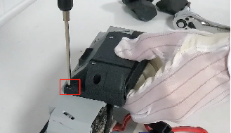 |
| Step 2: remove one screw on the copper bar of positive and negative power supply | 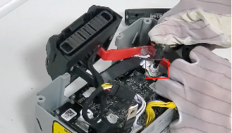 |
| Step 3: remove the battery plug assembly | 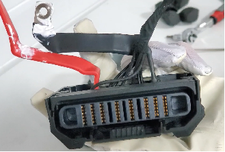 |
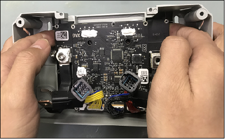
Step 4: Remove the battery mainboard
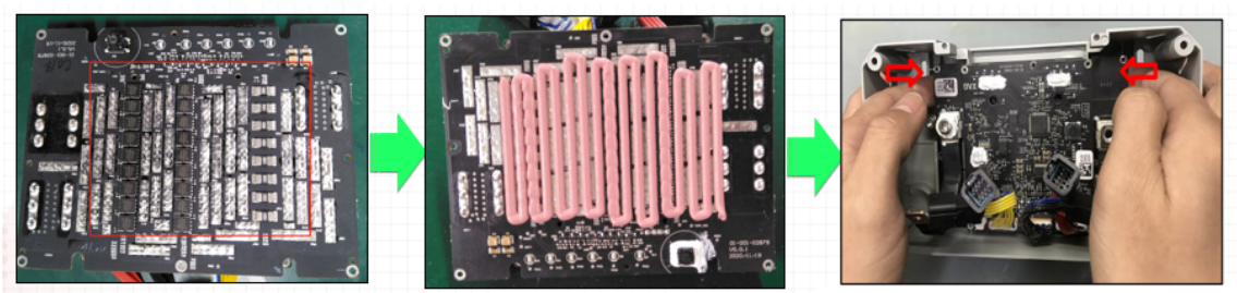
| Step 1: remove the 14 screws on the main board and power board. | 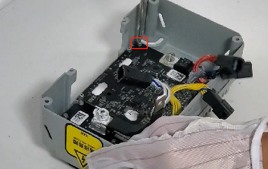 |
| Step 2: remove the main board and slowly buckle up both ends of the power board with two index fingers. Let the power board naturally separate from the head shell from top to bottom. when removing the main board, it is forbidden to pull out the connecting wire directly by hand |
|
| Step 3: remove the fuse fixing screw. Remove the fuse. |
|


Step 5: Remove the battery plug
| Step 1: remove the fixing screws of the battery plug baffle | 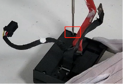 |
| Step 2: remove the battery plug baffle | 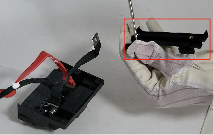 |
| Step 3: remove the battery plug | 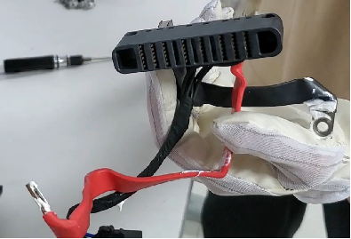 |
Step 6: Remove the battery cell
| Step 1: remove the two screws on the battery separator | 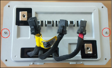 |
| Step 2: lay the battery flat, hold the battery and slowly take out the battery cell in the direction of the arrow 1. It is forbidden to pull the connecting wire on the electric core directly by hand;Pay attention to prevent scratching during taking the electric core. 2. Insulating materials, such as foam / anti-static leather, shall be prepared and laid on the workbench; 3. The table top of the workbench shall be kept clean and tidy without other sundries. |
 |
Battery assembly process and precautions
1. Battery assembly process
- Assembling the battery mainboard
- Assembling battery cells
- Assemble connecting wire
- Assemble the battery case
2. Precautions for battery assembly
- For the assembly of thermal conductive silicone grease of power board, live operation is strictly prohibited, and anti-static measures shall be taken
2. When assembling the electric core, it is forbidden to lift the connecting wire on the electric core;
3. When assembling the battery, pay attention that the battery head shell cannot contact the positive and negative poles on the cell at the same time, resulting in short circuit
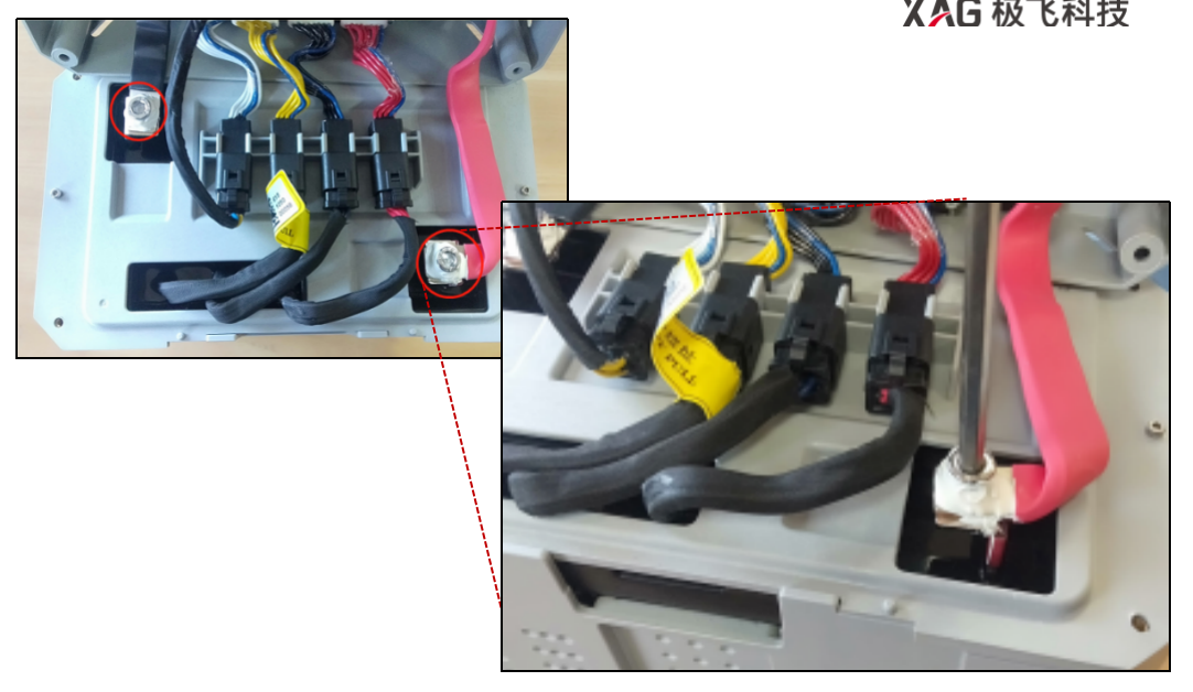
4. When assembling the battery, after locking the screws on the positive and negative connectors of the power line, it is necessary to apply silica gel according to the following figure 

5. Before assembling the cell, check that the wire is intact, the QR code sticker is complete and identifiable, and the appearance of the cell is free of deformation and bulge.
6. When assembling the connecting line of the cell and the head case, the first negative pole, and then the whole machine, and then in accordance with the order and color of yellow, black, red plug line, can not plug wrong.

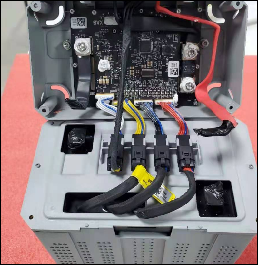
7. Connecting line arrangement

Troubleshooting process of B13960S
General troubleshooting summary
Troubleshooting 1: The power button does not respond
Troubleshooting 2: Two battery level lights are flashing and the power light double flashing
Troubleshooting 3: The battery level lights are running
Troubleshooting 4: Charging fault
Troubleshooting 5: Battery lock
Troubleshooting 6: Abnormal temperature sensor
Troubleshooting 7: The battery is locked and cannot be unlocked
Troubleshooting 8: Fuse installation and detection
| Troubleshooting 1: The power button does not respond | |
| Troubleshooting method: A. Check whether the cell voltage is normal (whether the total measured voltage is between 43.2 ~ 50.4v), and judge whether cells problem causes the fault. If it is not the cell fault, it is the mainboard that needs to be replaced |   |
| Troubleshooting 2: Two battery level lights are flashing and the power light double flashing | |
| Troubleshooting method(fualt lock): A. Connect the battery to the computer and use the battery tool software to check the battery information for abnormalities such as large pressure difference, large temperature difference and low cell voltage. |
A. Cells voltage difference: Static differential voltage is less than 30mV The load differential voltage must be less than 60mV |
| B. Use the battery tool software to check the battery information data. If there are obvious abnormalities, replace the main board kit and battery cell respectively with the replacement method to judge the fault point (first, check whether the main board kit and battery cell have external deformation, liquid corrosion, component falling off and other poor appearance) | |
| C. If there is no obvious abnormality in the battery data checked by the battery software, it is necessary to use the high-power electronic load instrument to test whether the battery is abnormal. | |

| Troubleshooting 3: The battery level lights are running | |
| Troubleshooting method(Battery upgrade failed): 1.Troubleshooting method: turn on the battery, connect the computer, and use the battery tool to upgrade |
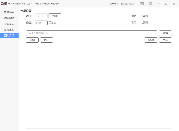 |
| 2. The faulty battery can be plugged into the aircraft to start up, the firmware can be copied into the flight control mode for upgrading and troubleshooting, and the firmware can be asked by the XAG technician. | |
| Troubleshooting 4: Charging fault | |
| Troubleshooting method: A. Check the charging port for dirt, deformation and poor communication caused by liquid inlet; | 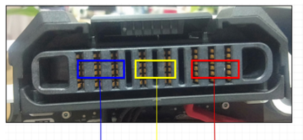 |
| B. Abnormal cells, such as abnormal cell temperature or differential pressure; | |
| C. The battery mainboard is filled with liquid, which is caused by circuit failure (troubleshooting by replacement method); | |
| D. If the battery is locked, contact XAG technicians to unlock it or use the battery tool; | |
| E. If the temperature of the newly flown battery exceeds the set value, the motherboard will protect the battery and prohibit charging. It is necessary to heat the battery in time. | |
| Troubleshooting 5: Battery lock | |
| Troubleshooting method: Battery lock: generally, there are two ways to unlock the battery lock when the power is too low: A. Contact XAG technicians to unlock it; |
 |
| B. Use the battery tool software to unlock with the computer | |
| C. The battery is locked due to poor battery cell or poor motherboard. At this time, it cannot be unlocked successfully. | |
| Troubleshooting 6: Abnormal temperature sensor | |
| Troubleshooting method: A. NTC resistance in the cell is abnormal, replace the cell; |
|
| B. Main board liquid inlet corrosion or poor detection circuit; | |
| C. Loose connection terminal or poor contact; |
| Troubleshooting 7: Alarm instructions on the mobile phone when the battery is in flight | |
| Alarm description 1: Low cell voltage Method: if the voltage of a single chip is lower than 3.5V, an error will be reported. Please return in time for charging; |
|
| Alarm Description 2: Discharge current too high Method: when the battery detection current exceeds the set value, an error will be reported;Check as follows: A. Check whether the propeller is installed correctly and whether each propeller is deformed and damaged. If there is no obvious deformation, it can be tested by replacing the propeller; B. Check whether the motor is normal, whether the motor base is horizontal, whether the boom and its fixings are deformed, and whether the propeller plane is the angle at the time of delivery; C. Check whether the voltage of each cell is unbalanced and whether the battery power is sufficient; D. In plateau areas, the dosage can be reduced; E. If the density of liquid medicine is too high, the dosage can be reduced; |
|
| Alarm description 3: Abnormal cell temperature sensor Methods: 1NTC of general cell is abnormal;2. Poor motherboard. |
|
| Alarm description 4: Loose plug Method: the battery is not plugged in properly on the drone, or the battery plug has poor contact due to aging;The tail plug of the aircraft is dirty and aging. |
|
| Alarm description 5: BMS abnormal Methods: generally, the plug connected between the battery cell and the mainboard is loose or the main board battery management fails; |
|
| Alarm description 6: Abnormal cells Method: generally, the load differential pressure of the cell is large after the cell attenuation. |
|
| Alarm description 7: battery over discharge Methods: when the total battery power is less than 10% or the single-chip voltage is less than 3.1V, the battery will be locked. You can contact Jifei technicians for remote unlocking or use computer tools to unlock. |
| Troubleshooting 8: Fuse installation and detection | |
| Troubleshooting method: 1. Turn the multimeter to the buzzer gear, connect the probe to the metal parts at both ends of the fuse, the multimeter buzzer rings, and the reading of 0 indicates normal, otherwise it is poor. | |
| 2. Install the fuse after replacing the new main board. Remove the silica gel of the old fuse before installation.Apply silica gel after locking the fixing screw (the fuse is at the bottom and the negative wire is at the top). |