UAV Components, Sections, and Systems
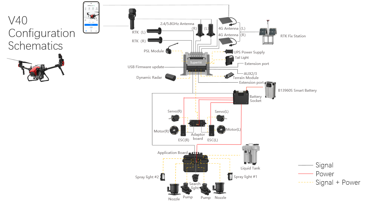
UAV Configuration Schematic
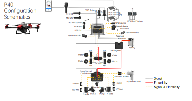
P40 Schematic
V40 Schematic
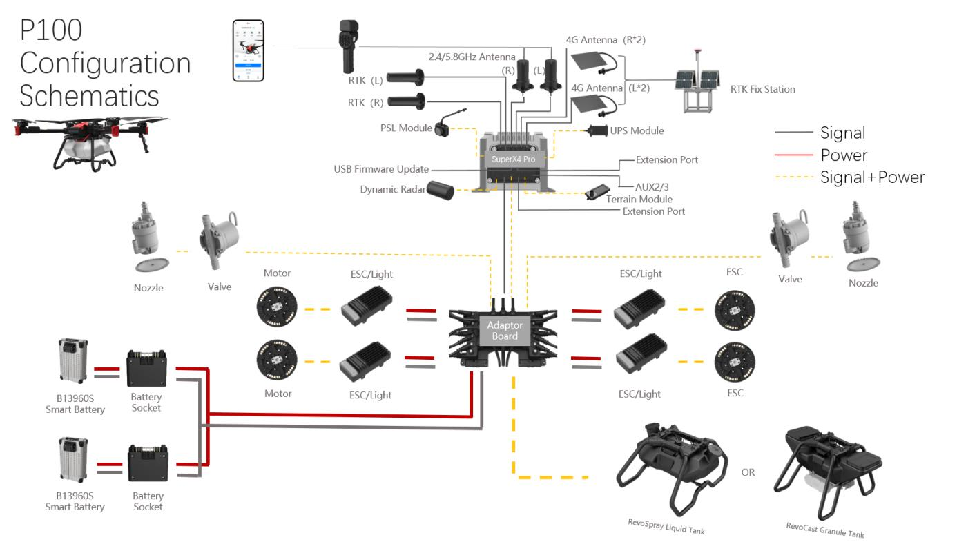
P100 Schematic
Propulsion System
Overview
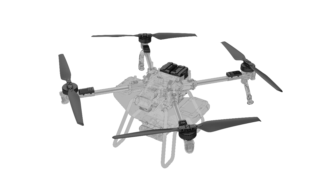
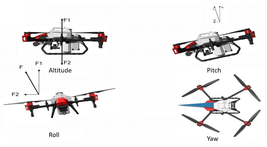
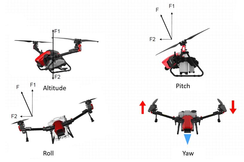
UAV propulsion system is the machine that produces force to run the aircraft. The force of flight consists of altitude, roll, pitch, and yaw. Air fluid is accelerated by the rapidly spinning propellers, and the reaction to this acceleration produces a force on the aircraft.
|
P40 |
V40 |
P100 |
|
|
Maximum Takeoff Weight |
49.1 kg |
45.8 kg |
88 kg |
|
Rated Takeoff Weight |
49.1 kg (Spraying) 49.1 kg (Spreading) |
45.8 kg (Spraying) 45.8 kg (Spreading) |
88 kg (Spraying) 51.5 kg (Spreading) |
|
Maximum Operating Flight Speed (Dynamic radar On/Off) |
10m/s |
8m/s |
13.8m/s |
*No matter that dynamic radar is on or off, their maximum operating flight speed are the same.
|
Model |
Hovering Duration * Tested in an environment near sea level with a wind speed of less than 3 m/s. For reference only |
|
P40 |
15 min (with no-load @20,000 mAh & takeoff weight: 29.1 kg) 6.5 min (with full-load @20,000 mAh & takeoff weight: 49.1 kg) |
|
V40 |
13.5 min (with no-load @20,000 mAh & takeoff weight: 29.8 kg) 6.8 min (with full-load @20,000 mAh & takeoff weight: 45.8 kg) |
|
P100 |
17min (no-load @20000mAh x2 & takeoff weight 48kg) 7min (full-load @20000mAh x2 & takeoff weight 88kg) |
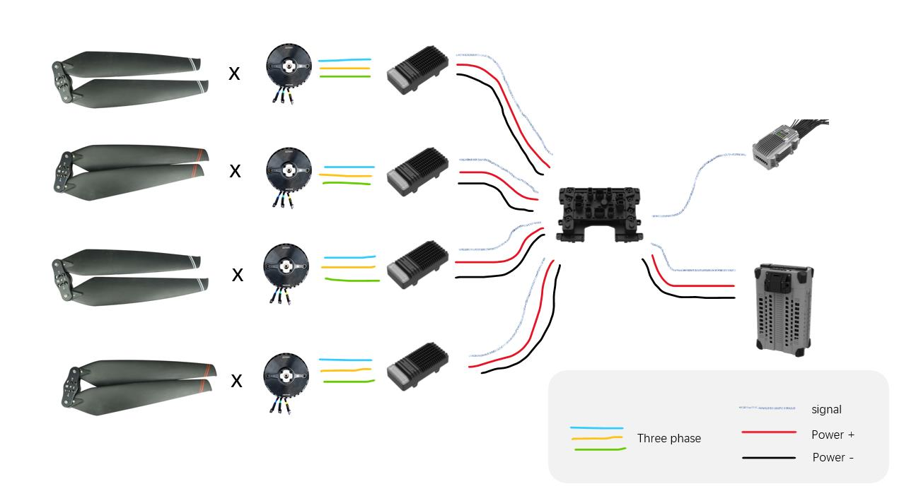
P100 propulsion system schematics
Attitude Flying: Establishing Control of the Aircraft’s Flight Path
Attitude provides information about an object's orientation with respect to the local level frame (horizontal plane) and true north. GNSS attitude solutions typically consist of three components: roll, pitch and yaw.
The easiest way to understand what we mean by attitude is to consider a plane with three linear axis running through it:
- Wing up/down = Roll
- Nose up/down= Pitch
- Nose left/right = heading/yaw/azimuth
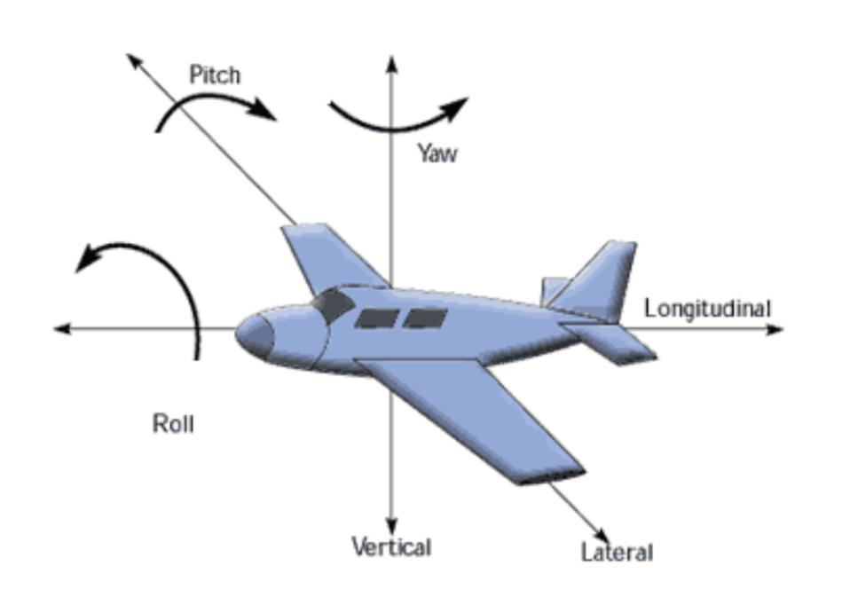
Angular measurement on the horizontal plane, with respect to true north, is referred to as yaw. Yaw is also known as azimuth or heading. The angular measurement on the vertical plane, with respect to the local level frame, is computed as pitch or roll.
Attitude measurements are important for precise positioning in UAV.
For XAG UAV, the attitude flying will looks like:
P40/P100:
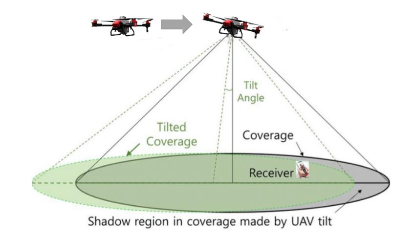
If the tilt angle reaches its limit, the UAV may lost balance and possibly crash immediately. To avoid this accident, please do not fly your drone when,
- Poor propulsion system
- Strong wind
- Heavy rain
- container is too full
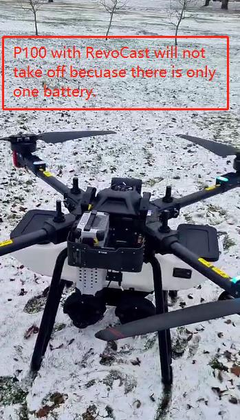
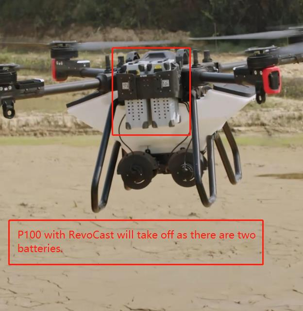
 Regarding to P100 RevoCast, its propulsion system requires at least two batteries to take off.
Regarding to P100 RevoSpray, its propulsion system requires at least one battery to take off.
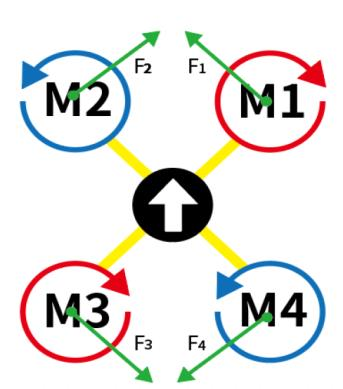
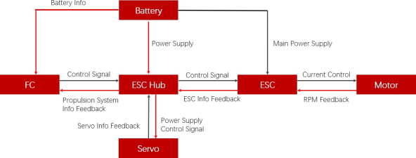
V40 Duo Propellers Drone Data flow
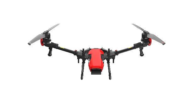
V40 attitude:
Motor (three-Phase Induction Motor)
The motor is used to convert an electrical form of energy into mechanical form. XAG uses three phase induction motor that operates on three phase supply. The construction is very simple and robust. It has mainly two parts. They are stator and rotor. The three-phase supply current produces an electromagnetic field in the stator winding which leads to generate the torque in the rotor winding of three phase induction motor having magnetic field.
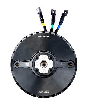
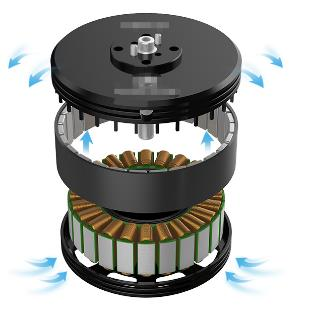


|
UAV Model |
Diagram |
|
P100 EN/CN P40 EN/CN |
|
|
V40 CN |
|
|
V40 EN |
|
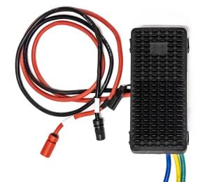
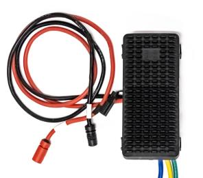
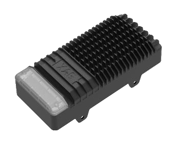
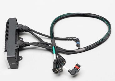
Electronic Speed Controller
The electronic speed controller (ESC) is an essential part of an UAV propulsion system’s hardware. It acts like the brain of the system by telling the motor how fast to go based on data signals it receives from the flight control. The role of the ESC is to act as the regulating middleman between the battery and the electric motor. It controls the rotation of the motor by delivering timed electric signals that are translated into changes in speed. It uses the direct current from the battery coupled with a switch system to achieve an alternating three-phase current that is sent to the motor.
Comparison Table of P40/V40/P100
|
P40 ESC |
V40 ESC |
P100 ESC |
|
|
photo |
|
|
|
|
LED indicator |
× |
× |
√ |
Foldable Propeller
Drone propellers are a replaceable part of a drone that generate airflow by rapidly spinning which acts as a propulsion system that creates lift and enables a drone to fly. Changing the speed of specific propellers enables it to ascend, descend, hover in place and it also affects the drone’s yaw, pitch, and roll.
|
P100 Propeller |
|
|
47" CW |
|
|
47" CCW |
|
Propeller tip up/down can weaken the vortex.

XAG propellers tips. Some tip up while others tip down. But both are proven to weaken vortex.
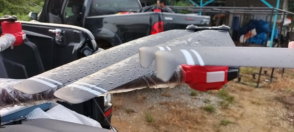
If you are not sure what vortex is. The below picture is the propellers vortex in fluid.
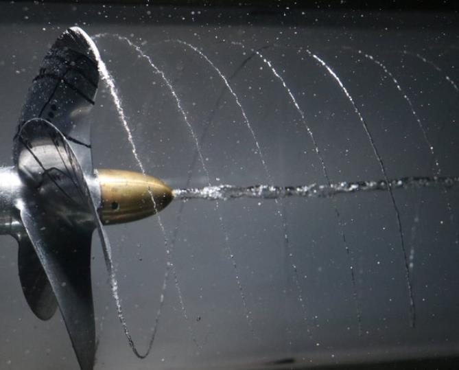
RevoSpray
Variants
|
P40 |
V40 |
P100 |
|
|
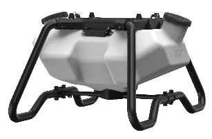
Tank photo |
|
|
|
|
Tank size |
20 |
16 |
40L |
|
Max. flow rate |
10L/min |
10L/min |
12L/min |
|
number of Peristaltic Pump |
2 |
2 |
2 |
|
Atomized droplet size |
60-400 μm |
60-400 μm |
60-400 μm |
|
Max. spraying width |
10m |
10m |
10m |
|
Adjustable spray bar |
× |
× |
√ |
|
magnetic float level transmitter |
√ |
√ |
√ |
P100 RevoSpray Structure
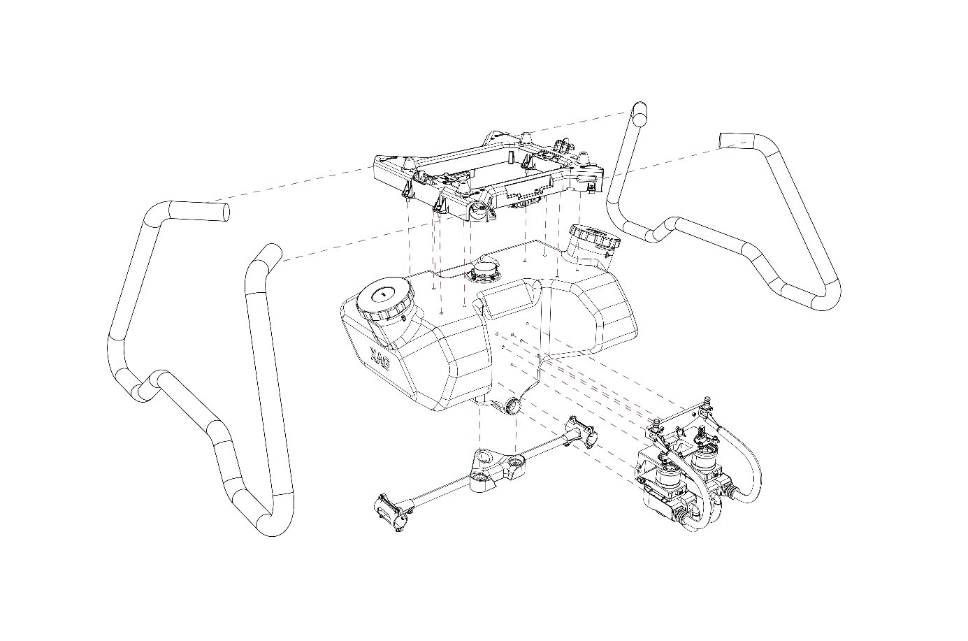
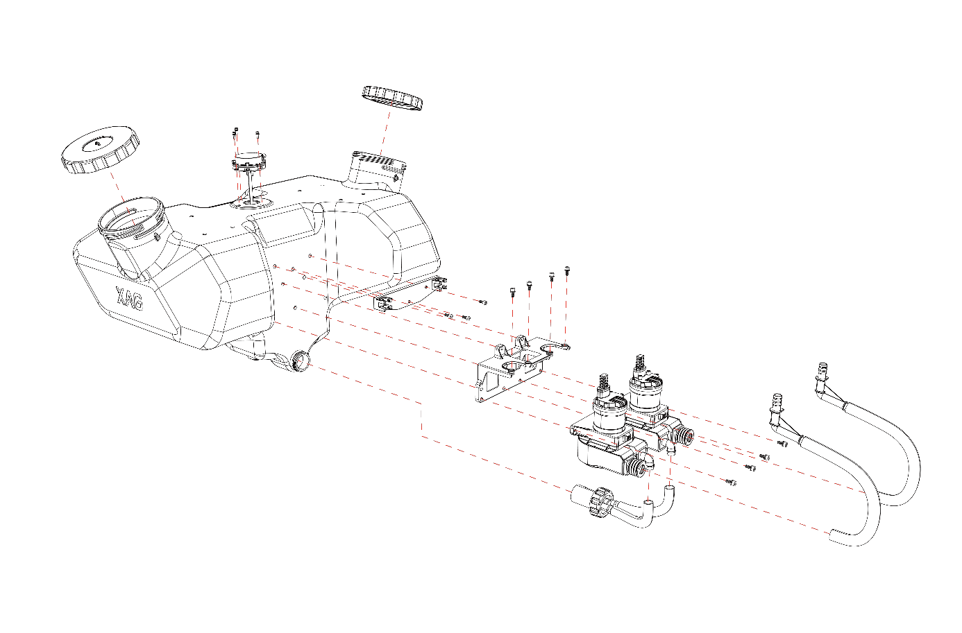
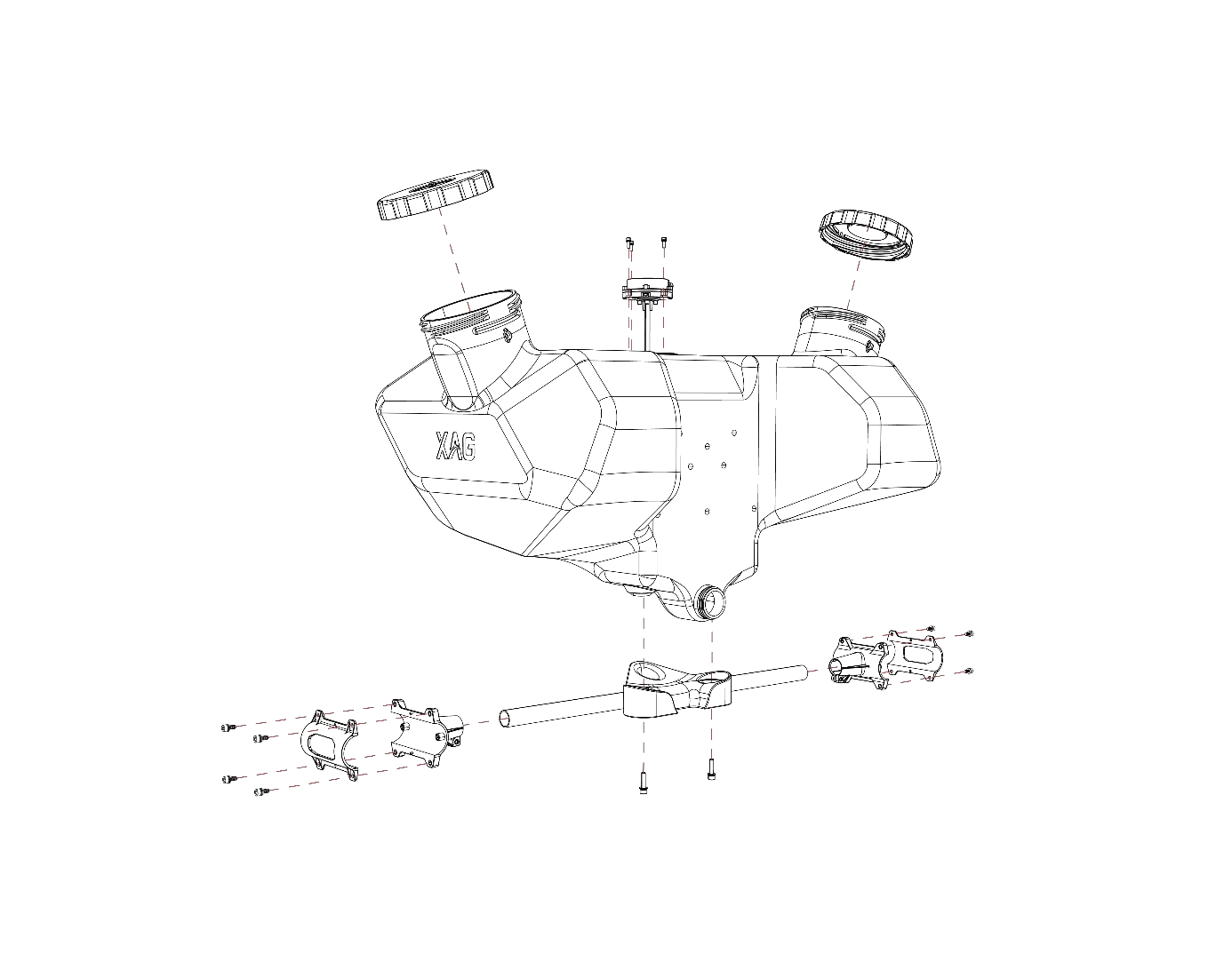
Basic Concept of Smart Liquid Tank
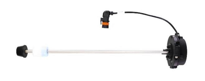
magnetic float level transmitter
A float moves with the liquid surface. Magnets within the float cause a change in resistance alonge a resist or chain built into the sensing probe. The change in resistance is used to calculate the level of the liquid. This design of float level transmitter is non-invasive and protected the electronics components from chemical erosion.


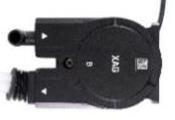
Peristaltic pump
A peristaltic pump, also commonly known as a roller pump, is a type of positive displacement pump used for pumping a variety of fluids. The fluid is contained in a flexible tube fitted inside a circular pump casing. The peristaltic pumps work through rotary motion. The rotor has 2 wipers attached to its external circumference, which compress the flexible tube as they rotate by. The part of the tube under compression is closed, forcing the fluid to move through the tube. Additionally, as the tube opens to its natural state after the rollers pass, more fluid is drawn into the tube. This process is called peristalsis and is used in XAG spray system.
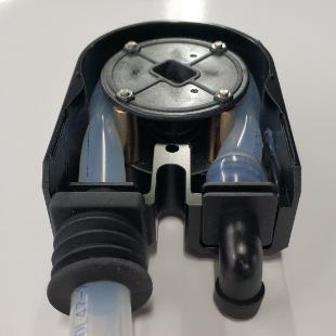
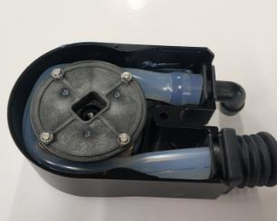
| No. |
Peristaltic pump motion in one cycle |
| 1 | 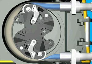 |
| 2 | 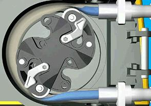 |
| 3 | 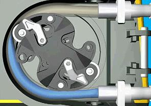 |
| 4 | 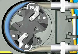 |
| 5 | 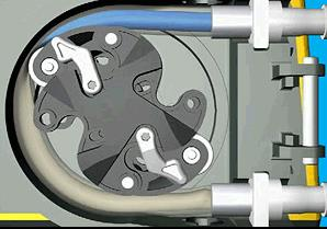 |
| 6 | 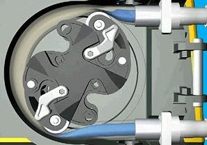 |
|
Peristaltic Pump |
V40, P40 |
P100 |
|
Photo (pump A, pump B) |
|
  |
|
Quantity |
2 |
2 |
|
Voltage |
50V |
50V |
|
Maximum System Flow Rate |
10L/min |
12L/min |
|
Maximum Flow Rate (Single Pump) |
5L/min |
6L/min |
|
Installation |
Under fuselage |
Detachable Liquid tank |
RevoCast 2 for P100
Introduction
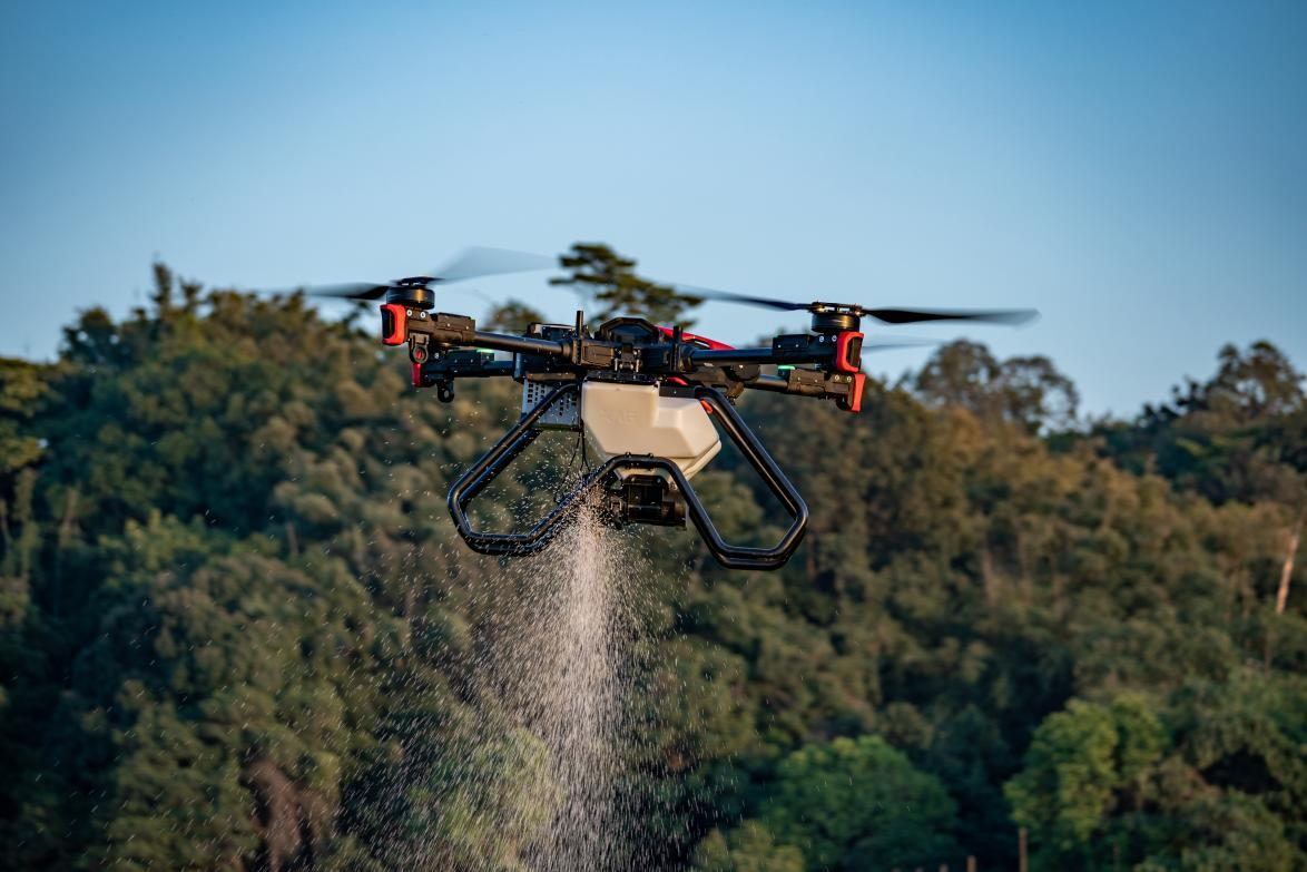
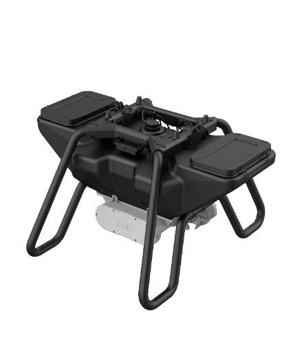
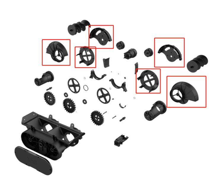
RevoCast 2 is a spreading system designed for P100. It adopts a brand-new design for spreading disc and screw feeder, reshape the spread methodology of agricultural drones that greatly enhance the efficiency and accuracy of spreading granules.
Structure
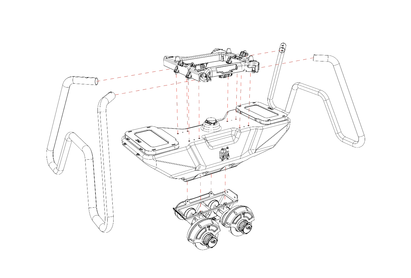
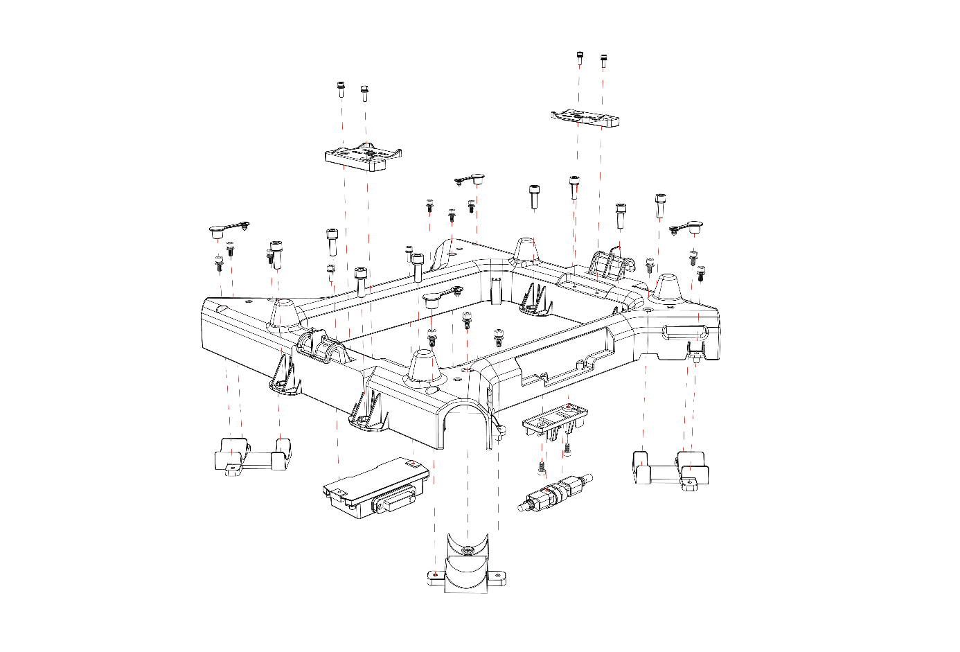
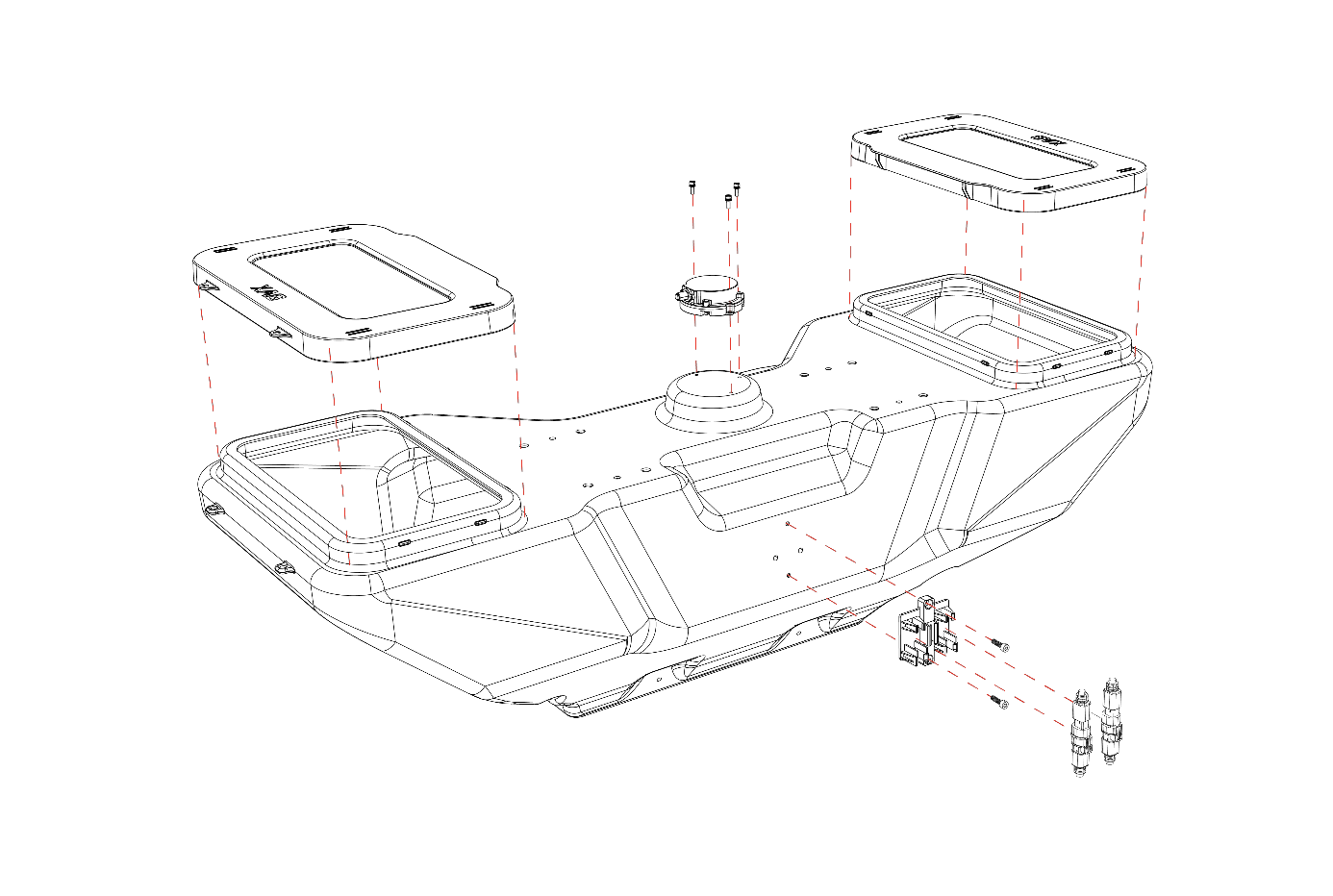
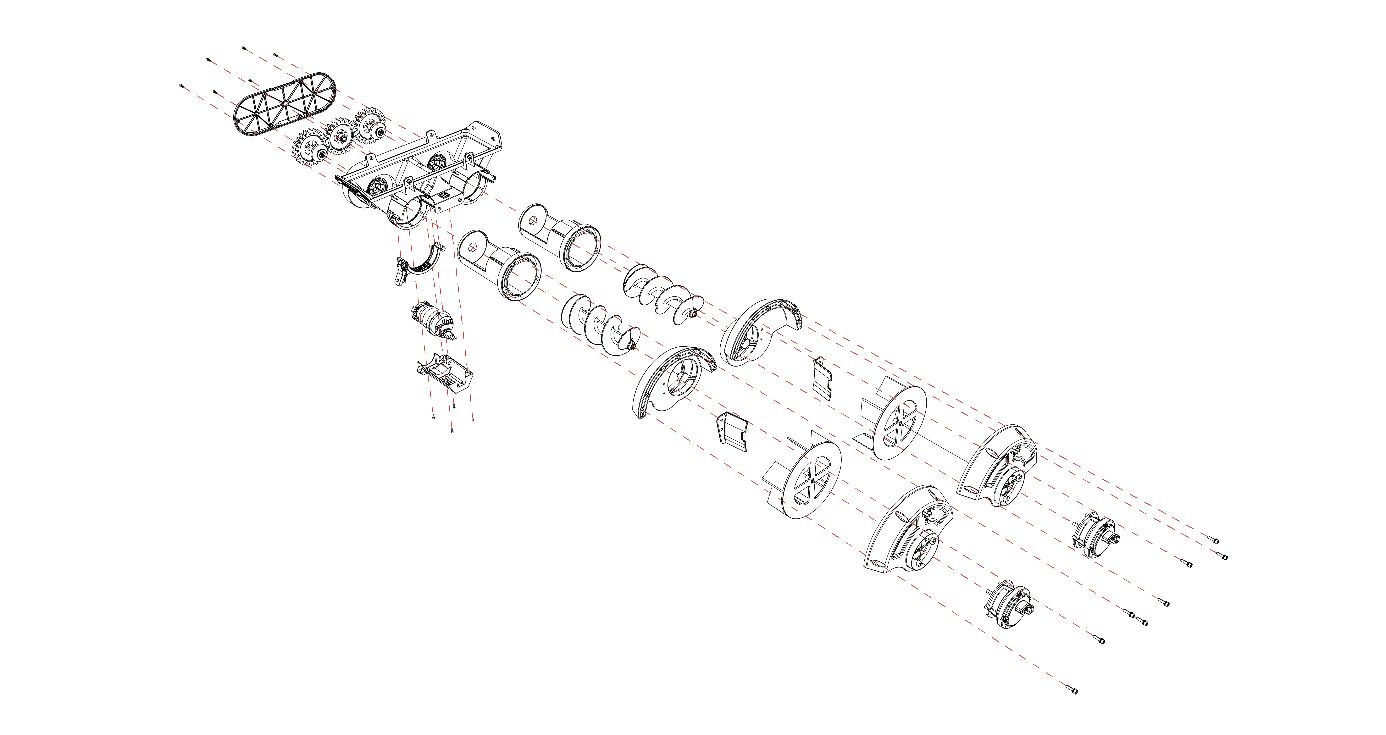
Main Component

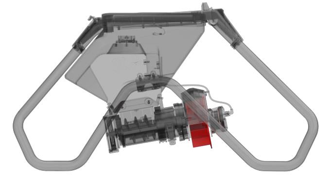
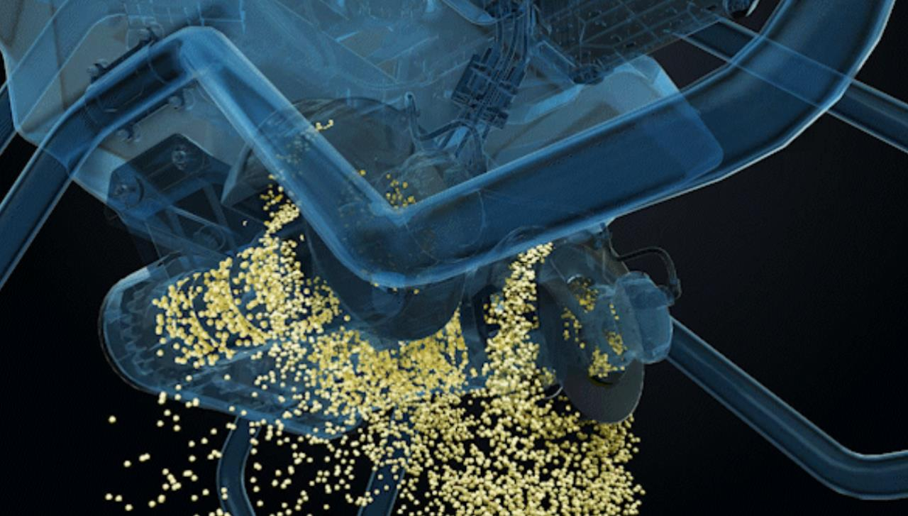
The two key mechanical parts of RevoCast system is the spiral feeder and spreading disc. The spiral feeder is used to control the flow of granules.
The spread disc is used to control the spread width.
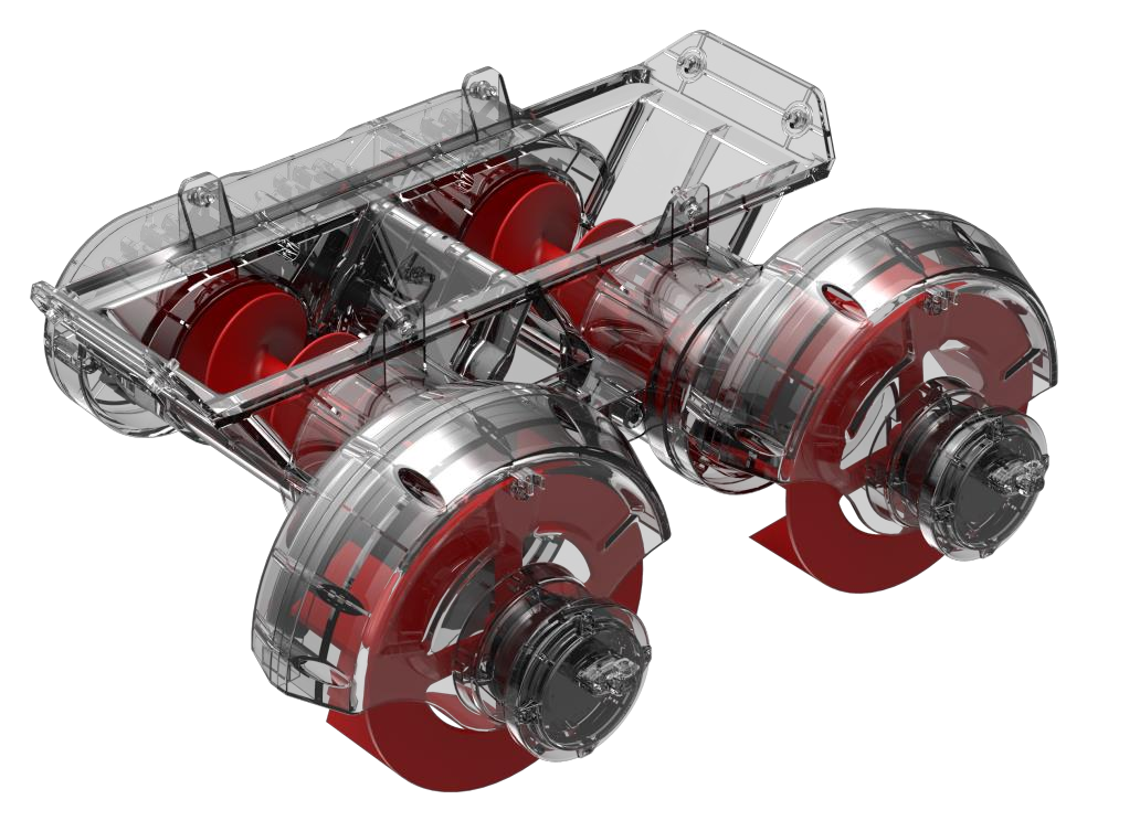
Fast release
Fast release allows user quickly clean or change spiral feeder.


Application system cable hub
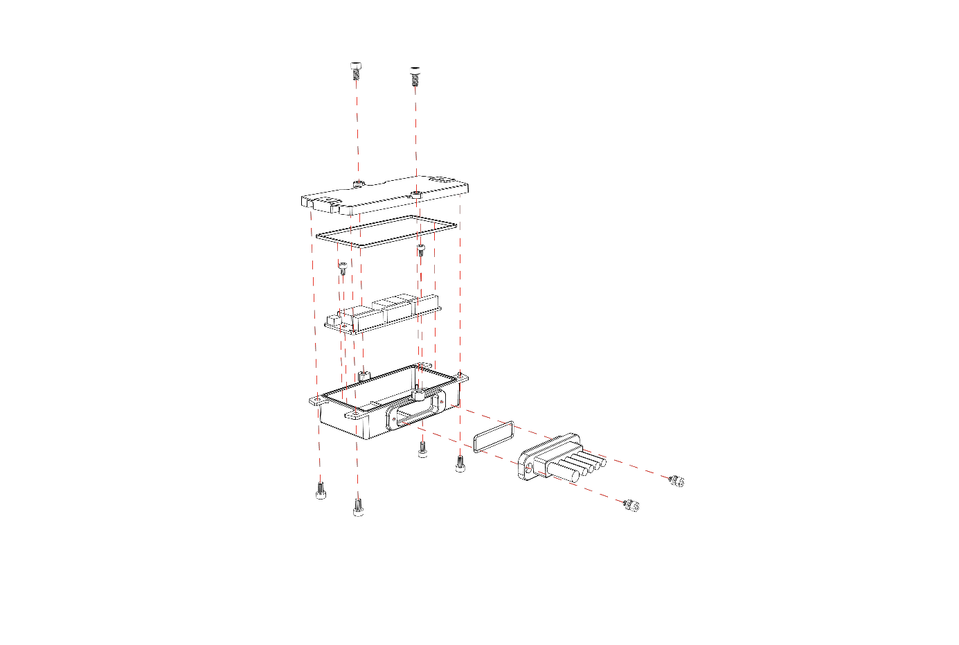
Application system cable hub contains the high voltage circuitry that controls RevoCast operation.
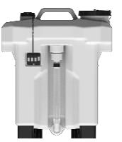
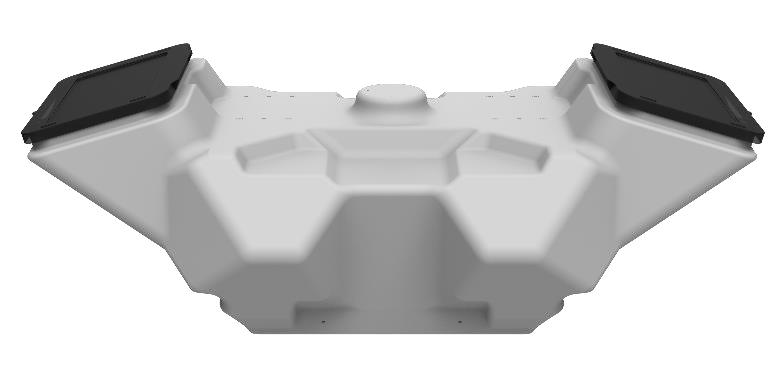
Granule Container
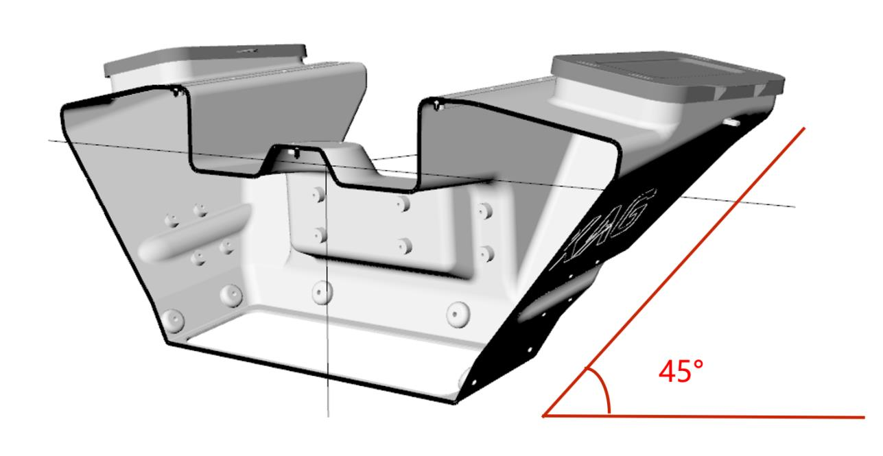
Granule container has the funnel shape that allows the granule naturally moves to the bottom.
The trapezoid shape allows granules flow downward smoothly, and minimize granules trapped in side the container.
Spiral Feeder Motor
Spiral feeder motor allows the rotation of spiral feeder.
The spiral feeder motor and ESC are sealed inside the


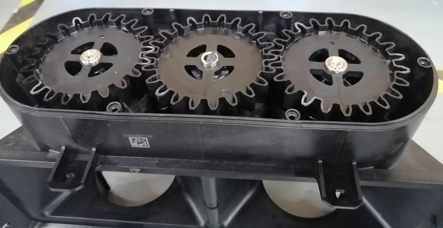
The gear mark should be align with base line.
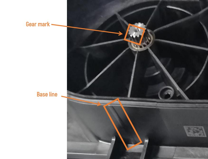
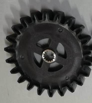
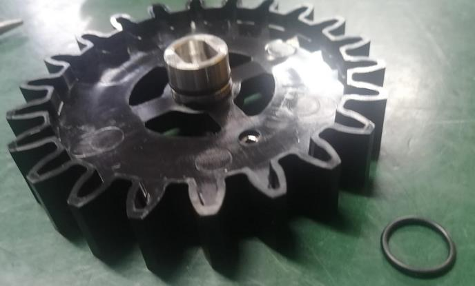
The pictures of synchronized gear:
|
synchronized gear of spiral feeder |
Synchronized gear of spiral feeder motor |
|
|
|
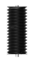
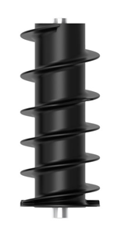
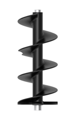
Spiral Feeder
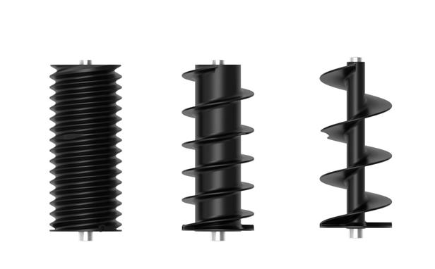
Spiral feeder is used to deliver granules to spreader disc in certain rate. During the flight mission, the UAV will generally speed up or slow down. To ensure the dosage per hectare, the spiral feeder rotation rate will adjust accordingly.


It’s important to know that there are three sizes of spiral feeder. They are large, medium, small respectively

Please be aware of that A magnet on spiral feeder is used for measuring the spiral feeder stop position.
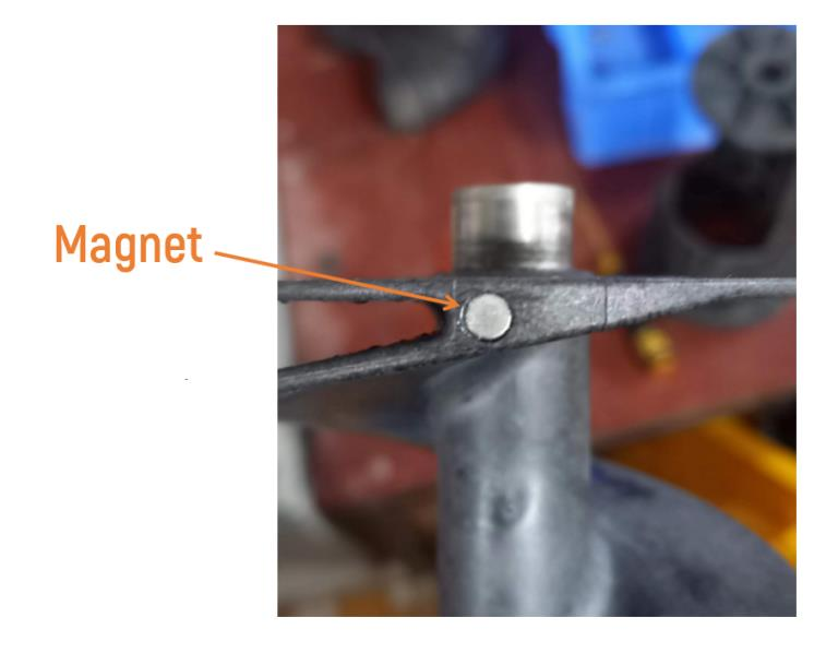
If magnet is loss, the spiral feeder will no longer work and need to be replaced.


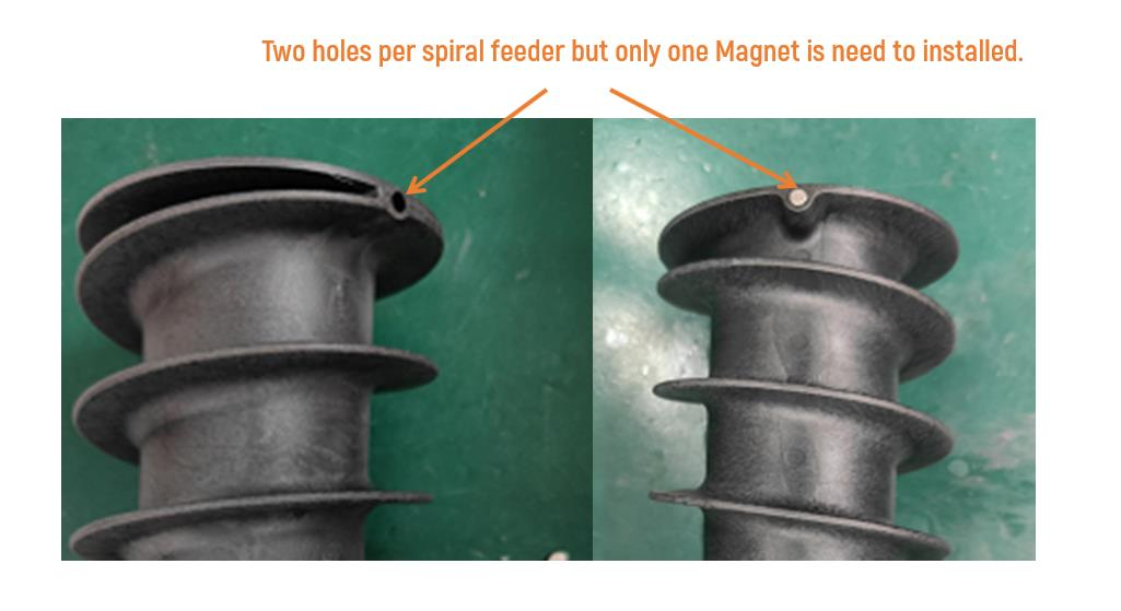
There are two holds on one spiral feeder but only one magnet needs to be installed.
Spreader Motor
Spreader motor is used to rotate spreader disk.


Spreader Disc
Spreader Disc is used to uniformly distribute granules.
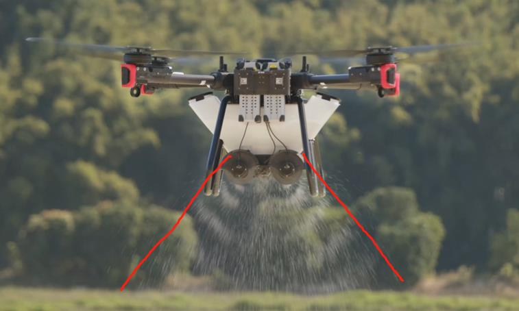
Two spreader disc is installed vertically. Spreader disc can apply force on granules, so that granules can reach the speed above 20m/s. Assumed the flight height is 6 meters, the spreader disc can shoot the granules onto the ground surface within 0.3 second. Benefit from this short of time, RevoCast spreading can eliminate the granules misplacement due to wind.

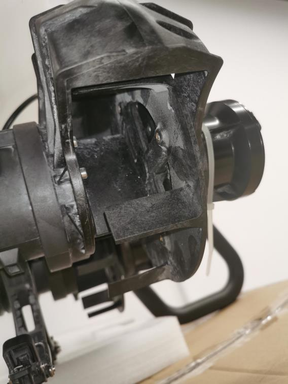
Additionally, the spreader disc is designed like a wheel with teeth, which will avoid the physical harms on seed.
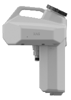
Granule Level Sensor
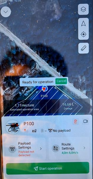
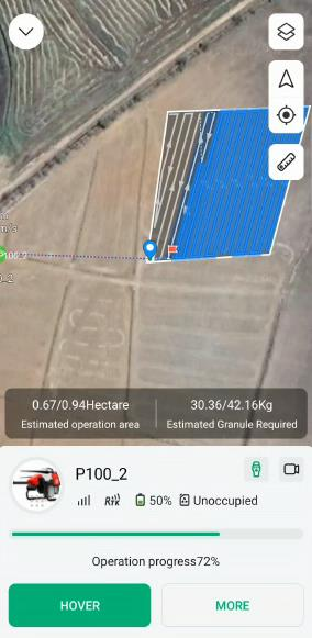
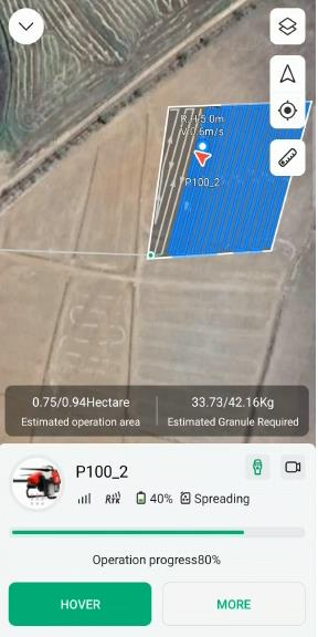
Level sensor can detect if the granule container is empty. This sensor is not capable of estimating the remaining quantity of granules inside container. Thus, the XAG One App will NOT display the remaining quantity of granule. Instead, it will display three unique status. They are offline, unoccupied, and spreading respectively.
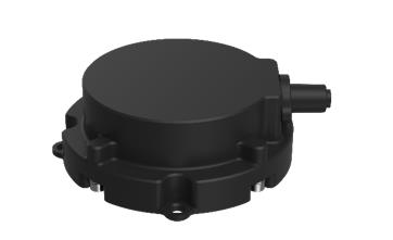
The image of level sensor
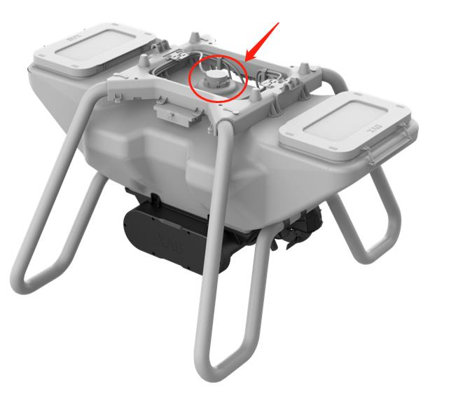
The position of level sensor
To better understand the status, please refer to the below table
|
No. |
Status |
Description |
Photo |
|
1 |
No payload |
Disconnected/ system malfunctioned. |
|
|
2 |
Unoccupied |
Idle/ inactive |
|
|
3 |
Spreading |
Spreading in process |
|
Spreading Performance on Dosage
Spreading granules distribution test results (only for reference)
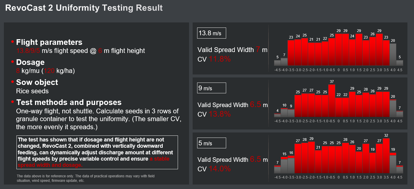
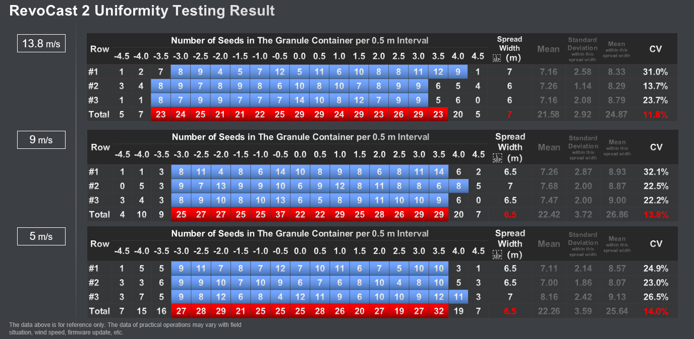
Selecting the proper size of spiral feeder?
Need to consider the dosage per hectare, flight route, flight speed, spray calibration, granules shape and size, spread width.

Where,
|
Parameters |
Description |
Unit |
|
Total dosage |
Total consumption of granules |
kg |
|
Spread Calibration Rate |
Calculated by calibration process. It can differ as the change of granules type and spiral feeder size |
r/kg |
|
Motor Speed |
Spiral feeder motor, rotation per minutes |
r/minute |
|
Total Area |
Total area of each flight |
 |
|
Flight Speed |
UAV flight speed, related to ground speed |
m/s |
|
Spread Width |
The width that RevoCast can cover |
m |
Dosage error may come from,
- Spiral Feeder Motor: The minimum rpm of spiral feeder is 1000 The best performance of motor is approximately between 4000 and 9000 rpm. Please be aware of that the closer the spiral feeder motor reaches the limitation of rotation speed, the worse performance it has, which means the greater the error of dosage per hectare will be.
- Spreading Calibration: spreading system must be recalibrated for each type of granule or the change of spiral. Otherwise, significant error will happen.
- Dosage per hectare: Use proper range of dosage per hectare. If the consumption of dosage per hectare is too low, the spiral feeder motor will inevitably decrease its rotation This will result in spread error.
- Flight Route: It’s suggested to have less turns in UAV spreading flight routes. Because this will cause dosage When the aircraft is turning, it must slow down or stop the spiral feeder motor to keep the dosage per hectare unchanged. The spiral feeder motor error take place during slow down or stop.
- Flight speed: The flight speed will have major impact on RevoCast operation. Similar with the reason from flight route, the RevoCast spreader must keep the dosage per hectare unchanged during the flight mission. If UAV speed up, the RevoCast will decrease the granule flow. If UAV slow down, the RevoCast will increase the granule. If the granule flow gets too low or too high, dosage error will occur.
- Granule density: if the granule density is uneven, it will lead to dosage
- Spread width: Spread width is controlled by spreader. Similar with flight speed, it can affect the dosage error.
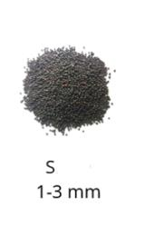
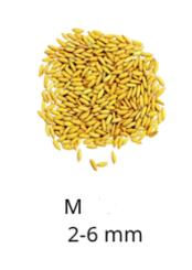
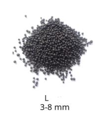
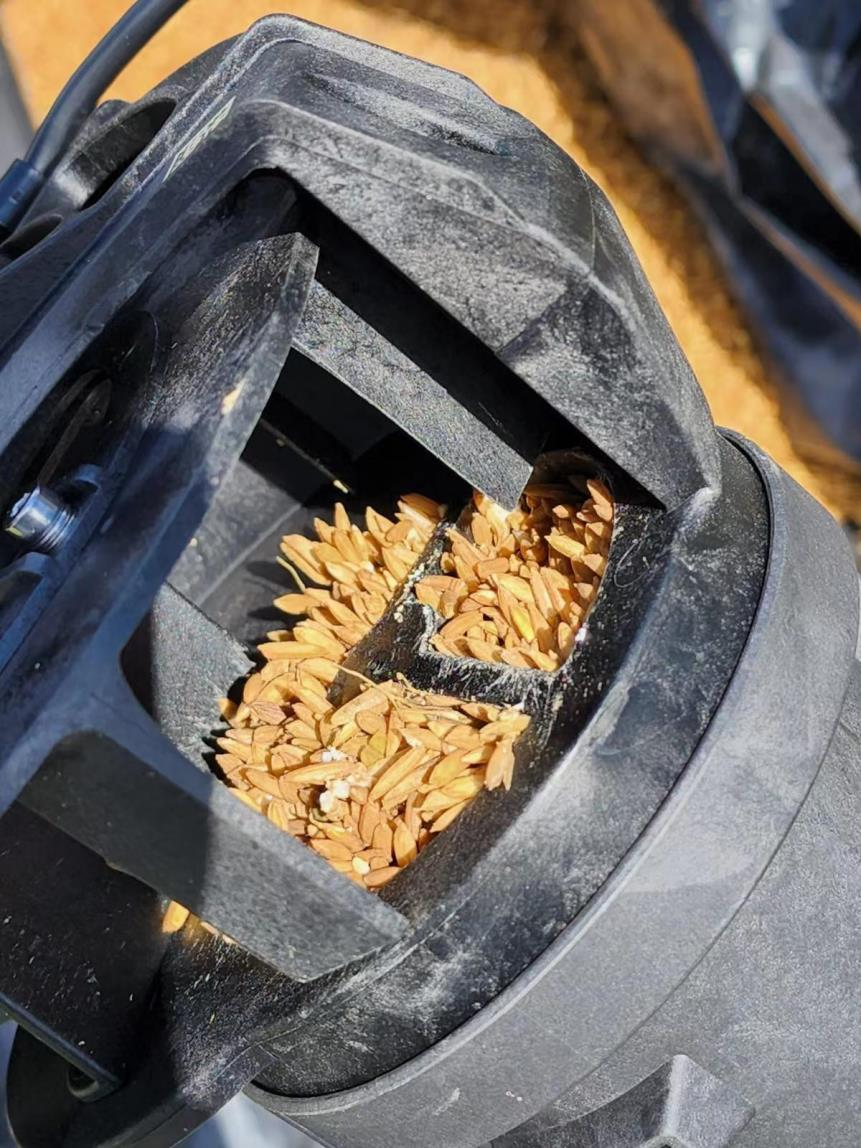
- Granule shape and size: select the appropriate auger to ensure no material jamming (suggestion: spread fertilizer in large size, rice in medium size, rapeseed in small. The auger shall be replaced reasonably according to the amount per mu)
There are three options for spiral feeder size. Please select the proper size of spiral feeder before use.
|
Spiral Feeder Size |
Photo |
Scenario |
|
Small |
|
Select small spiral feeder for the diameter in the range of 1~3 mm, or using low usage per hectare |
|
Middle |
|
Select medium spiral feeder for the diameter in the range of 2~6mm, or using medium usage per hectare |
|
Large |
|
Select large spiral feeder for the diameter in the range of 3~8mm, or using high usage hectare |
If the wrong spiral feeder size is applied, it could result in jam or dosage error.
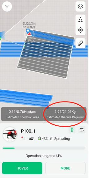
 The value of “Estimated granule required” is only for reference, as it is calculated by APP, not detected by RevoCast.
Obstacle Sensing & Avoidance System
Dynamic Radar
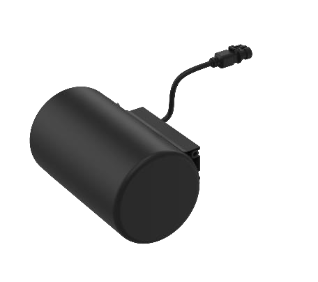
Dynamic radar works in millimeter wave with operating frequency of 24GHz. As a non-contact sensor, dynamic radar can scan and detect incoming obstacles during flight. It’s capable to detect the obstacle’s size, position, distance, vector direction, and speed within 40 meters ahead and above to achieve prediction and bypassing. Please be aware of that Dynamic radar can be significantly influenced by obstacle’s size, material, and speed. Thus, user should not completely rely on dynamic radar during obstacle avoidance. Instead, all the obstacles should be marked in field mapping.
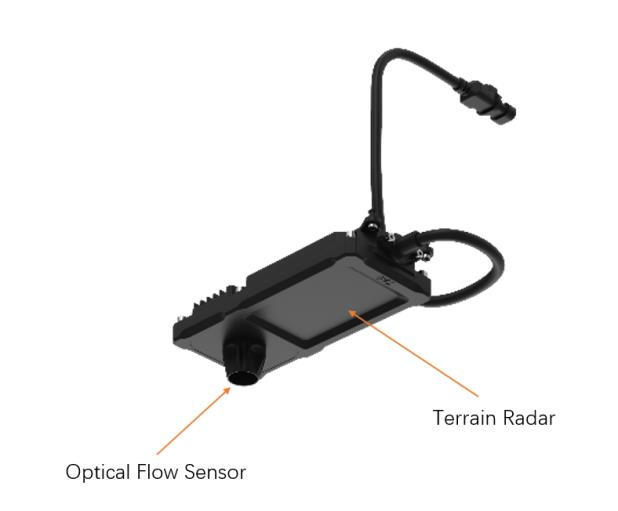
Terrain Radar & Optical Flow Sensor
The terrain radar works in in millimeter wave with operating frequency of 24GHz. As a non-contact sensor, terrain radar can scan and measure the vertical distance from the UAV and ground. Users can either turn on or off terrain following mode before flight mission. If the terrain following mode is enable, the terrain radar will consistently measure the vertical distance to the ground or obstacles (trees, roof, etc). Please be aware of that the terrain radar will be automatically activated if the measured vertical distance is less than 1.5m.
An optical flow sensor is a vision sensor capable of measuring optical flow or visual motion and outputting a measurement based on optical flow. Its configuration is an image sensor chip connected to a processor programmed to run an optical flow algorithm. This will allow the UAV to maintain its hovering position when the GNSS/RTK is lost.
Communication and Positioning System
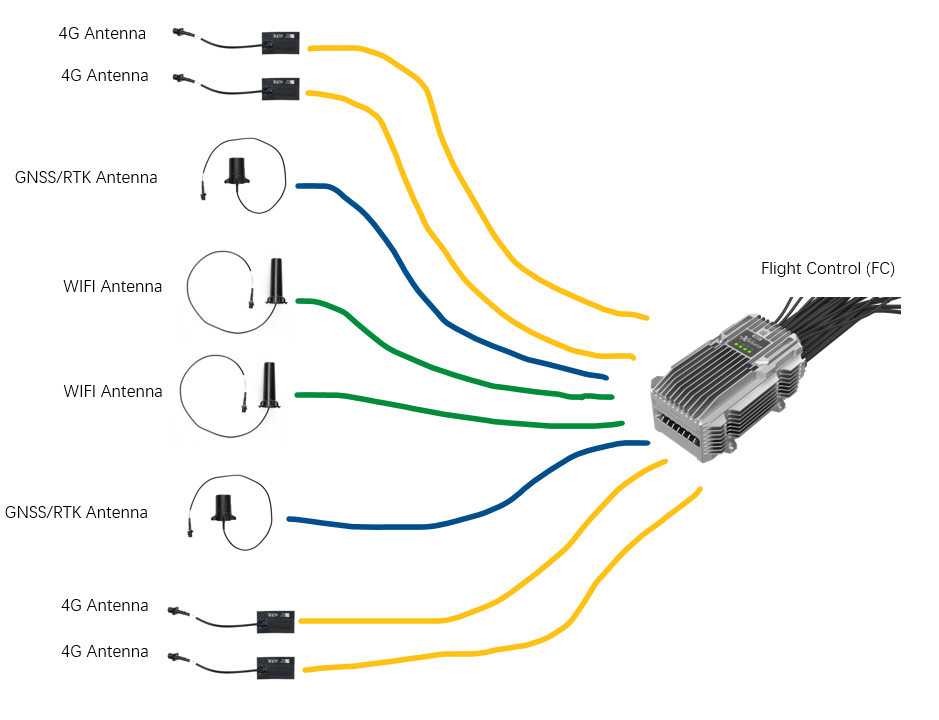
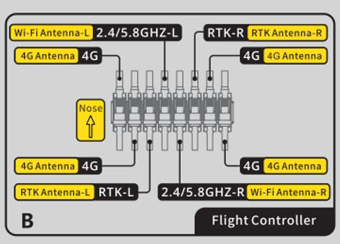
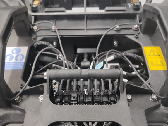
Overall Antenna Layouts
Wiring of 4G antenna, GNSS/RTK antenna, WIFI antenna and flight control
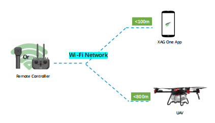
WiFi Communication system
Application
WiFi Communication system is used to link remote controller and UAV.

Types of remote controller:
|
No. |
Remote Controller |
Photo |
|
1 |
ACS2 2021 |
|
|
2 |
ARC3 Pro |
|
WIFI antenna
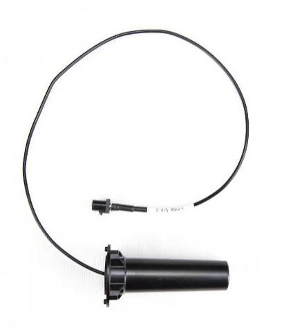
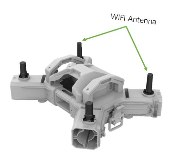
WiFi antenna is wireless networking device that converts the EM waves into electrical signals, and vice versa. There are two WIFI antenna on the drone. One is on the left of the fuselage; Another one is symmetrically on the right.
|
WIFI Antenna Photo |
WIFI Antenna Position |
|
|
|
|
Electrical Characteristics |
|
|
Frequency |
2400-2500 / 5150-5850 MHz |
|
V.S.W.R. |
<= 2.0@2400-2500MHz / 2.5@5150-5850 MHz |
|
Antenna Gain |
3.50 / 3.65 dBi |
|
Polarization |
Linear |
|
Environmental |
|
|
Operation Temperature |
- 40 ˚C ~ + 80 ˚C |
|
Storage Temperature |
- 40 ˚C ~ + 80 ˚C |
|
Waterproof |
Yes |
|
Simulation of 2400MHz |
|
|
4G Communication System
4G module
The main difference between Chinese version and English version is the 4G module.
|
ACS2 2021/UAV |
4G Module |
Frequency Bandwidth |
Comments |
|
Domestic version or Chinese version |
EC20-CN |
LTE-FDD: B1/B3/B5/B8 LTE-TDD: B34/B38/B39/B40/B41 WCDMA: B1/B8 GSM: B3/B8 |
It’s compatible with telecom bandwidth in China but not in other countries. |
|
International version or English version |
EG25-G |
LTE-FDD: B1/B2/B3/B4/B5/B7/B8/B12/B13/B18/ B19/B20/B25/B26/B28 LTE-TDD: B38/B39/B40/B41 WCDMA: B1/B2/B4/B5/B6/B8/B19 GSM: B2/B3/B5/B8 |
It’s compatible with most telecom bandwidth all round the world. |
Distinguishing Chinese / English Version (4G bandwidth difference)
|
Item |
Chinese version |
English version |
|
V40 |
3WWDZ-15.2A |
3WWDZ-15.2AH |
|
P40 |
3WWDZ-20B |
3WWDZ-20BH |
|
P100 |
3WWDZ-40A |
3WWDZ-40AH |
|
ACS2 2021 |
ACS2 |
ACS2G |
Device versions are displayed in the nameplate.
For example, P100 English version nameplate

P40 Chinese version nameplate.
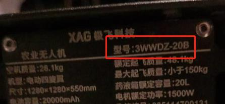
4G LTE antenna
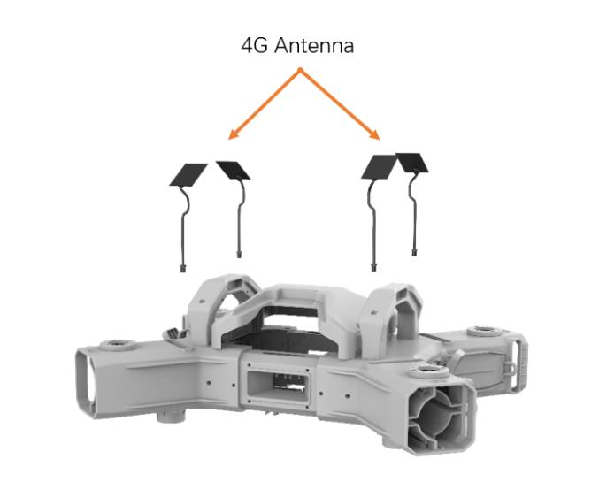
In telecommunications, Long-Term Evolution is a standard for wireless broadband communication for mobile devices and data terminals, based on the GSM/EDGE and UMTS/HSPA standards. It improves on those standards' capacity and speed by using a different radio interface and core network improvements. Because LTE frequencies and bands differ from country to country, only multi-band UAV (globe version) can use LTE in all countries where it is supported. 4G LTE antenna is used to transmitting data on the physical layer using 4G LTE technology.
|
4G Electrical Characteristics |
|
|
Frequency |
824-960MHz,1710-2690MHz |
|
V.S.W.R. |
@<4.0 |
|
Antenna Gain |
>1dBi |
|
Polarization |
Linear |
|
Environmental |
|
|
Operation Temperature |
- 40 ˚C ~ + 85 ˚C |
|
Storage Temperature |
- 40 ˚C ~ + 90 ˚C |
|
Waterproof |
No |
|
4G Antenna Photo |
Position |
|
|
|
Please be aware of 4G antenna installation.


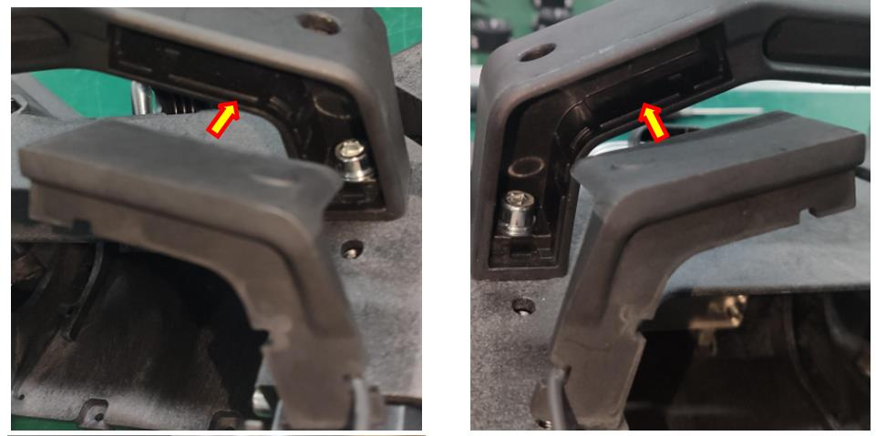
According to the antenna ideal simulation, we can know the signal coverage is not uniform in all direction, but let’s say 800m on average. 4G antenna is susceptible to wireless interferences. There are many obstacles in the fields that interference your WIFI signals - the main culprits being trees, terrain, buildings etc.
|
Simulation of 960MHz |
|
|
|
Simulation of 5800MHz |
|
|
Positioning System
P100/P100 Pro: Positioning Options
List of positioning option
- GPS
- RTK
- RTKstation
- Portablestation (RCN/LNT)
- Portablestation (4G)
- Fixstation (4G)
- VRTK
- CORS
- RTKstation
RCN Positioning compatibility
|
Positioning |
Local RCN |
Standard RCN4G |
Direct RCN4G |
RCNWiFi |
|
Portable station |
Supported |
supported |
supported |
Supported |
|
Fix station |
Not supported |
supported |
supported |
Supported |
|
CORS |
Not supported |
supported |
supported |
Supported |
|
GPS |
supported |
supported |
supported |
supported |
|
VRTK |
supported |
supported |
supported |
supported |
Positioning Option #1: XRTK4 positioning
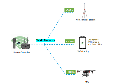
Positioning Option #2: VRTK positioning
Vrtk is called virtual rtk. You can imagine that when the drone is unmoved and stays in the take off position, it works as temporary portable rtk base station. Thus, when the drone takes off, it uses the virtual RTK position as base station reference.
This accuracy of VRTK is between RTK and GPS.
The VRTK must adjust its accuracy every 2 hours.
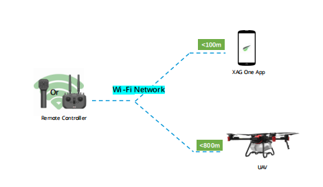
Positioning Option #3: RC networking mode with GPS positioning
The drone only uses GPS to take off, fly and land.
GNSS/RTK antenna
A Global Navigation Satellite System (GNSS) is defined as a group of satellites strategically placed to generate and relay positioning, timing, and navigation data from space to connected sensors on the earth. GNSS uses satellite technology to provide insight into connected devices’ geographic locations. GNSS is an inclusive term for the category of global systems, including:
GPS (United States)
GLONASS (Russia)
BeiDou (China)
Galileo (EU)
QZSS (Japan)
GNSS combined with RTK is a solution that can realize real-time precise positioning, and the positioning accuracy reaches centimeter level. It is used in application scenarios of UAV operation that the flight route and take-off/landing points requires high-precision positioning.
|
GNSS/RTK Electrical Characteristics |
|
|
Frequency band |
GPS L1/L2/L5/L-Band BDS B1/B2/B3 GLONASS L1/L2/L3 GALILEO E1/E5a/E5b/E6 |
|
V.S.W.R. |
<2.0 |
|
Antenna Gain |
33±2dBi |
|
Polarization |
Circular |
|
Environmental |
|
|
Operation Temperature |
- 40 ˚C ~ + 70 ˚C |
|
Storage Temperature |
- 55 ˚C ~ + 70 ˚C |
|
Waterproof |
IP67 |
|
Humidity |
95% with no condensing water |


Please be aware that the GNSS/RTK antenna can be only used in the open field.
Control System
Flight control
Flight controller also called FC for short, stabilizes and controls a UAV for semi-autonomous and autonomous flights. It is one of the core components of a UAV. Flight controller primarily consists of a microcontroller, control circuit & a suite of sensors (gyroscope, accelerator, electronic compass, barometer, etc.). It has redundant sensors & power supplies and performs redundant switching in case of failure to ensure flight safety.
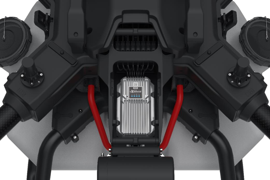
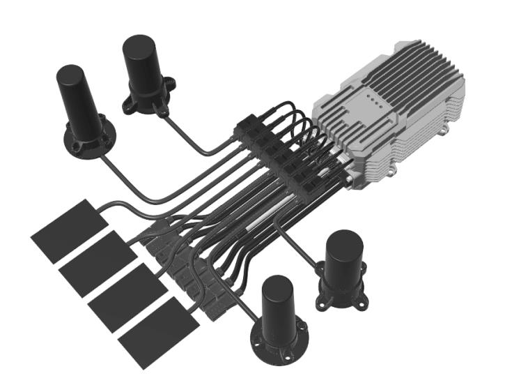
Use SuperX4 Pro as an example, it adopts real-time control unit, positioning navigation unit, data link and service unit, and spray & spreader control unit.
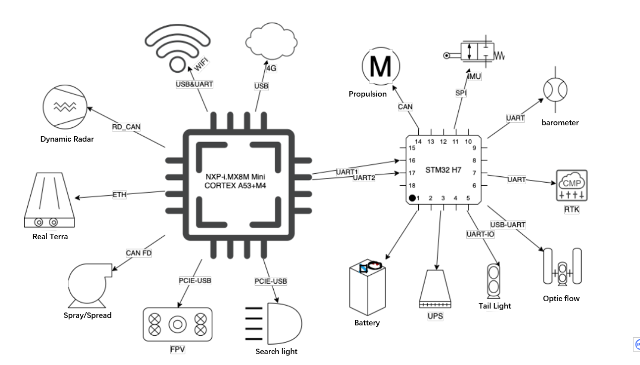
The real-time control unit and spray & spreader control unit adopt STM32H743 M7 core processor made by ST. Its CPU clock speed can reach up to 400MHz, 2MB maximum Flash, 1MB RAM; The positioning navigation unit adopts UM982, equipped with a three-axis accelerometer and gyroscope, barometer that can be auxiliary height measurement sensor.
The data link and service unit adopt NXP-i.MX8M Mini QUAD CORTEX A53+M4 processor made by Amlogic. Its CPU clock speed can reach up to 1.8GHz and it offers 16GB RAM, EMMC 5.1 storage and 2GB LPDDR4 running memory, on-board EC20-CN dual 4G module, WiFi module, interface ports that allows the communications with various peripherals.
Flight logs analysis requires years of professional UAV experience. Please contact XAG technicians for help.
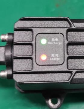
UPS
UPS is a backup power supply dedicated for flight control. The purpose of UPS is to continue provide electricity to flight control if the main power source (smart battery) is cut off. It mainly consists of power management board, three pieces of 18650 lithium-ion battery.

|
UPS discharge (to FC) |
UPS charge (from B13960S battery) |
Flight control powered by |
|
|
UAV Battery on |
No / Red light |
Yes / Green light |
Battery (B13960S) |
|
UAV Battery off |
Yes / Green light |
No / Red light |
UPS, approximately 2~5 minutes |
.png?height=120&name=Pegasus%20Robotics%20Logo%20-%20Portait%20(2).png)
