.png?height=120&name=Pegasus%20Robotics%20Logo%20-%20Portait%20(2).png)
Power Supply
B13960S Smart Battery
Overview
B13960S is the smart battery that has 13 lithium packs, with approximately 960Ah. To protect your battery, please
- do not overcharge or over-discharge
- do not use or store in cold weather, below 10 Celsius degrees
On/Off operation
How to turn on the battery? (2 long presses):
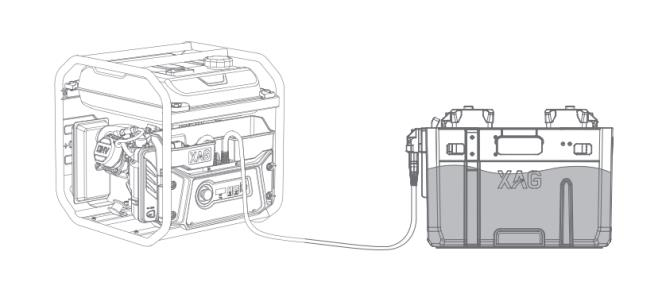
- In the shutdown state, connect to the load and press the power button for at least 1 second
- Wait for all power lights to flash at the same time then release the power button
- Press and hold the power button again for at least 1 second until the battery beeps and the status indicator lights up
How to turn off the battery? (2 long presses):
- In the power on state, long press the power button for at least 1 second
- Wait for all power lights to flash at the same time then release the power button
- Press and hold the power button again for at least 1 second until the battery beeps and the status indicator goes out
Introduction
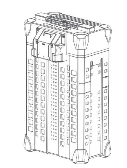
The B13960S intelligent battery (hereafter referred to as “the battery”) has a capacity of 20000mAh at a voltage of 48.1V. The metal shell and rubber caps protect the battery, and 13 high energy battery plate cells and advanced power management system allow it to provide power to an aircraft.
This intelligent battery contains 13 high-capacity lithium polymer batteries and integrates BMS module. It can monitor voltage, current, temperature and others status information in real time. During the use of battery, BMS can give real-time feedback to the UAV flight control. When the battery is insufficient or out of work, the BMS system will actively send an emergency stop command to ensure safety.
The B13960S smart battery is composed of head shell, mother board, partition plate, battery cell, tail plug, lower shell, etc.
|
Charge with Intelligent SuperCharger |
Charge with Auto SuperCharge Station |
 |
 |
Battery Compatibility
The B13960S Smart Battery is compatible with XAG's 2021, 2022 and 2023 agricultural UAV and vehicle.
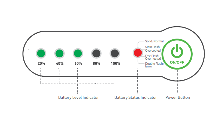
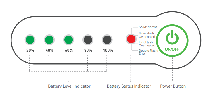
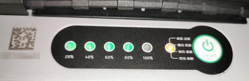
Check Battery Status

B13960S status indicator: Anti-dismantling lock will disable the use of battery. The battery cannot be used if the battery cell or motherboard is replaced without battery tool activation. Technically, repair staff need to contact XAG technical support team when replacing battery head or mother board. Battery cells are not allowed to be replaced due to safety concerns.
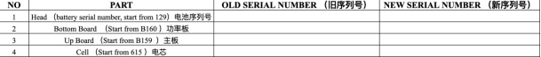
Battery Parts and Serial Numbers
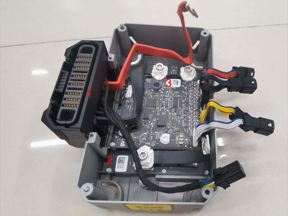
The major modules of a B13960S’ include the battery head and battery cell. The BMS is installed in the battery head, including
1: the battery socket, no serial number
2: the interface board (lower layer). It has a serial number beginning with B160
3: the main control board (upper layer). It has a serial number beginning with B159
The battery cell module consists of 13 cells. The module has a serial number beginning with 615 or 6242.
Changing Battery Parts
Every XAG battery has a unique Serial Number with a QR code printed beside the led indicators. Together with the serial numbers of the main board, interface board and the battery cell module, these 4 SNs are bounded as a combination in the battery management system. To change any parts of the battery, it needs to unbind the original and get a new combination.
If you need to change any one of the 4 parts of the battery, please provide the following combination data to the tech support of XAG for recombination. After that, you are required to use the battery tool and software to activate the battery (please look up “Activate Battery”).
Data sheet available on the google drive mentioned in Appendix of this manual
Hardware
The below exploded view diagram shows the components of B13960S battery.
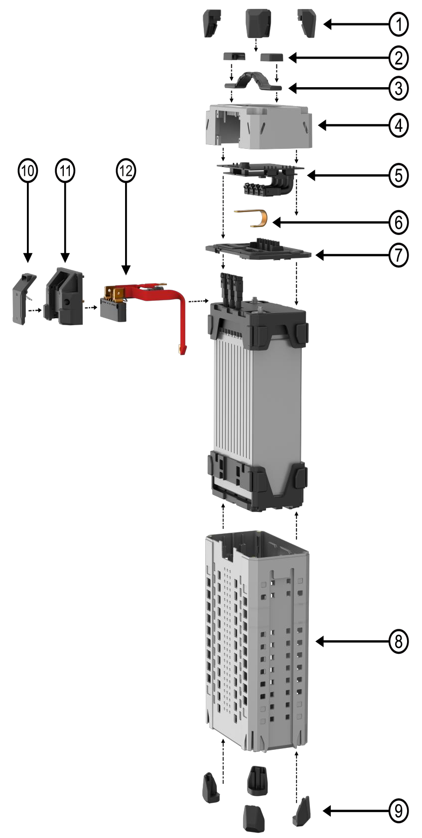
| No. | Part number | Part name |
| 1 | 02-001-00976 | B13860S,B13960S Battery Corner Rubber Pad (Bottom) |
| 2 | 02-001-06891 | B13860S,B13960S Battery Handle Bracket |
| 3 | 02-001-03656 | B13860S,B13960S Battery Handle |
| 4 | 02-002-07478 | B13960S Battery Top Casing |
| 5 | 14-004-00072 | B13960S Battery Motherboard |
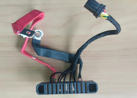
| 6 | 02-002-07223 | B13960S Negative Power Outlet Cord |
| 7 | 02-001-06622 | B13960S Battery Middle Deck |
| 8 | 02-001-06621 | B13960S Battery Bottom Casing |
| 9 | 02-001-02795 | B13860S,B13960S Battery Corner Rubber Pad (Bottom) |
| 10 | 14-004-00028 | B13960S Battery Clip Kit |
| 11 | 14-004-00027 | B13960S Battery Outlet Socket Housing |
| 12 | 01-027-01895 | B13960S Battery Outlet Socket |
Battery Motherboard
Battery motherboard consists of a mainboard and a power board.
Mainboard
The mainboard is physically attached to the power board. It is placed inside the battery head, used for collecting battery information, outputting, and controlling battery status. The mainboard has added nano coating technology to increase its waterproof performance and encryption authentication technology for safety concerns. After replacing the battery cell or mainboard, it is necessary to activate the power software system before use.
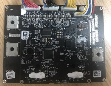
Battery mainboard
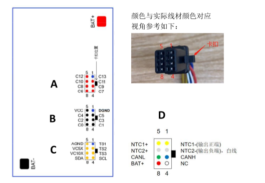
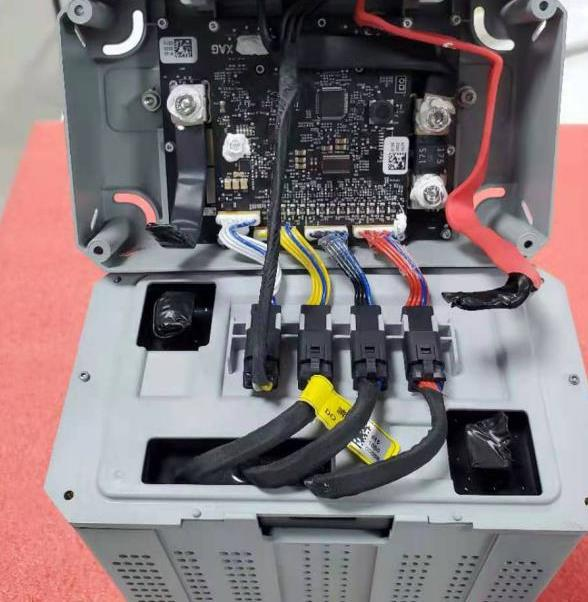
On the top of the mainboard, there are 4 plugs from left to right in sequence. The functions of each plug will be shown as below:
- Red 8 pin terminal – cell voltage detection for battery cell 6~13
- Black 8 pin terminal – cell voltage detection of battery cell 1~5
- Yellow 8 pin terminal – NTC(Negative Temperature Coefficient. Temperature detection and encrypted communication between battery cell and BMS
- White 8 pin terminal – communication line between BMS and UAV’s flight control
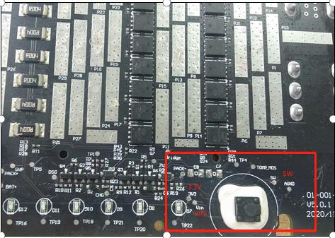
Power board
The power board is used for computation, the indication display, logic output (I/O), etc.
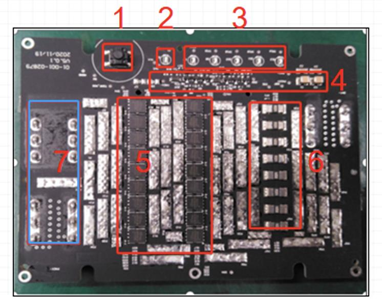
The highlighted area in the above picture are the major components of the power board.
1. Power button
2. Status indicator (normally solid red)
3. battery indicator
4. MOSFET control circuit. In general,MCU controls PWM waveform, and controls switching state of MOS via gate driver.
5. MOSEFT, control output on/off
6. Current sampling circuit (output current is sampled from both ends of the resistor). The sampling resistance is a resistance with a very small value, generally less than 1 ohm. There will be voltage when there is current flowing through it. The voltage at both ends is converted into voltage by an operational
amplifier. After the voltage is amplified, ADC is used for sampling and then connected to MCU. MCU knows how much the current is.
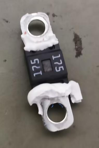
7. One flat plate fuse is added to the battery power board. The specification: 175A/57V is connected in series at the negative end of the battery output.
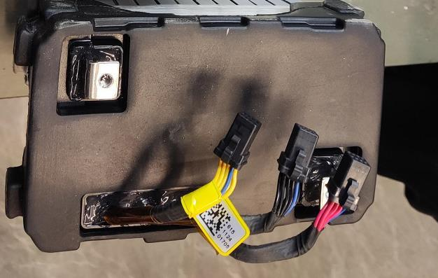
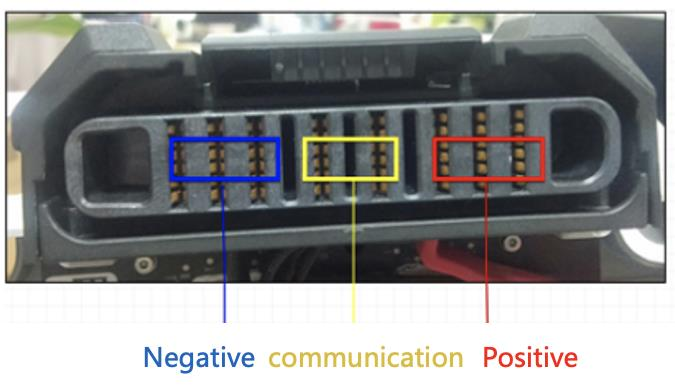
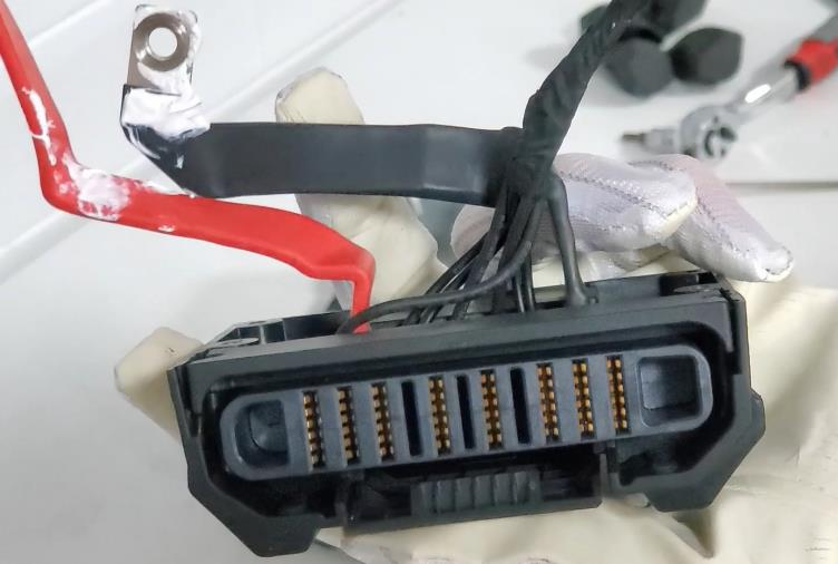
Battery plug
The battery plug is the interface for electricity transmission, charging and discharging, and the communication signal.
| Battery plug | battery Plug Ports |
 |
 |
Disassemble Guide
- Remove the battery head shell
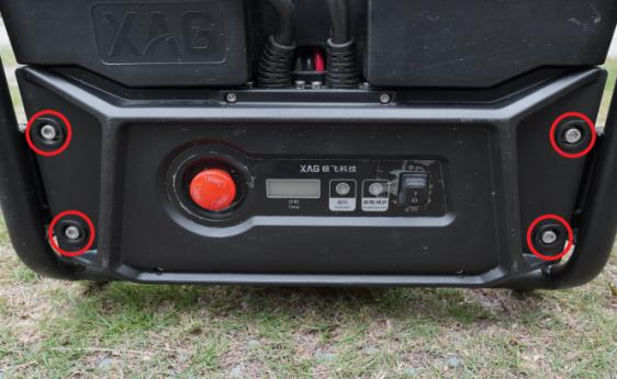
Step 1: Remove the 4 anti-collision rubber pads above the smart battery.
SSSSSSSSSSSSSSSSSSSSSSSSSSSSSSSSSSSSSSSSSSSSSSSSSSSSSSSSSSSSSS
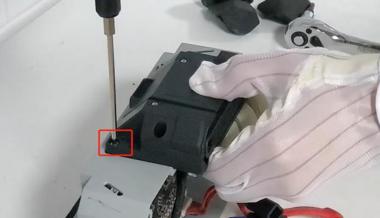
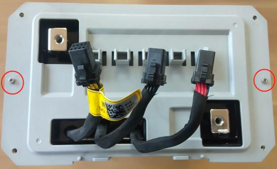
Step 2: Remove 4 screws from the upper shell of the smart battery


2. Remove the connecting wire
Step 1: remove two screws at the positive and negative terminal.
During the positive and negative terminal removal:
1. do not make contact between positive and negative terminal. Otherwise, it will result in short circuit.
2. wrap the exposed metal from terminal connector with insulating tape if necessary


Step 2: Remove 2 cell sensor wires, 1 temperature sensor wire and 1 signal wire connecting the battery cell and BMS intelligent battery management system.
 Caution:
When removing the core detection cable, the removal sequence must be
red cable(6-13S) →
black cable(1-5S) →
yellow cable (NTC temperature detection and encrypted communication)
white cable
3. Remove the battery plug
Step 1: Remove the 4 screws on the battery plug female holder.
Step 2: Remove one screw on the positive and negative copper terminal
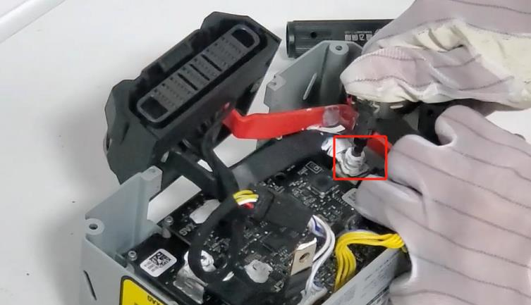
Step 3: Remove the battery plug
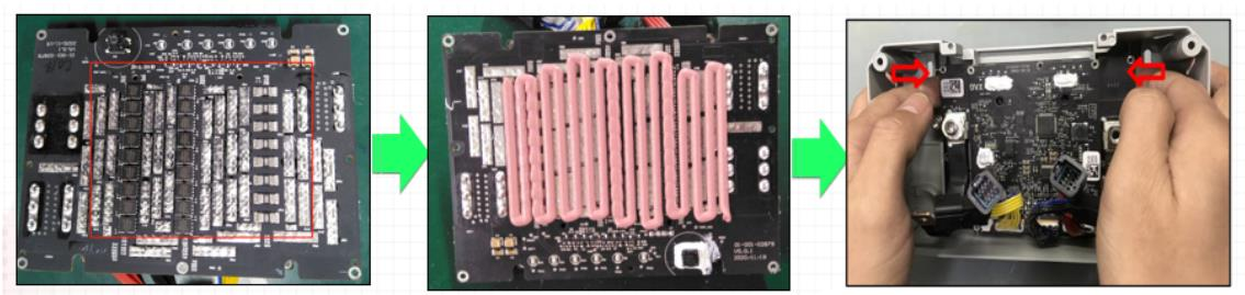
4. Remove the battery mainboard
Step 1: Remove the 14 screws on the mainboard and power board
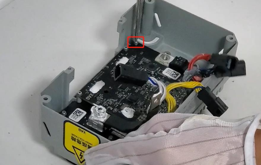
Step 2: Remove the mainboard and slowly buckle up both ends of the power board with two fingers.
Naturally separate the power board from the head shell from top to bottom.


Caution:
When removing the main board, it is forbidden to pull out the connecting wire directly by hand.
Step 3: Remove the fuse.


5. Disassembly the battery plug
Step 1: Remove the fixing screws of the battery plug case
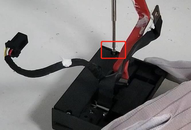
Step 2: Remove the battery plug case


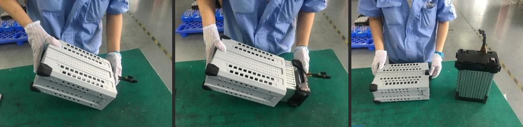
6. Remove the battery cell
Step 1: Remove the two screws on the battery separator.
Step 2: Hold the lower shell with two hands, and the upper part of the shell contacts with the table. Lift the bottom of the shell upward to keep a certain angle to ensure that the battery pack can come out of the shell. When the external dimension of the shell can meet the holding distance, take out the battery with one hand and place it vertically.
Please note the following content:
1. It is forbidden to pull the connecting wire on the electric core directly by hand, pay attention to
prevent scratching during taking the electric core


2. Insulating materials, such as foam / anti-static leather, shall be prepared and laid on the work bench.
3. The workbench shall be kept clean
Assembly Guide
Precautions for battery assembly
1. The thermal conductive silicone grease on power board is used for heat dissipation. It is strictly
prohibited to connect electricity, and anti-static measures shall be taken.
2. it is forbidden to lift the board by dragging or pulling the connecting wire.
3. It is forbidden to make contact between the positive and negative terminals, which will result in short circuit.
4. After tightening the screws on the positive and negative terminals, it is necessary to apply silica gel to seal the terminal contact (but don’t seal the screw teeth);


5. Before assembling the cell, check that the wire is intact, the QR code sticker is complete and identifiable, and the appearance of the cell is free of deformation and bulge.
6. Assembling sequence that connecting cables in the battery head, from a to f.
a) negative terminal
b) positive terminal
c) white signal cable
d) yellow signal cable
e) back signal cable
f) red signal cable


Practical Use
During operation
- Check the battery plug regularly during daily use. Clean it if necessary.
- If liquid is found on the battery during use, please clean it with a dry cloth in time to avoid short circuit.
- Before the flight, please check whether the firmware version of the battery is the latest version on the app. If there is a new version, please update it before operation. Each firmware update is to solve some known problems, so please make sure to update it.
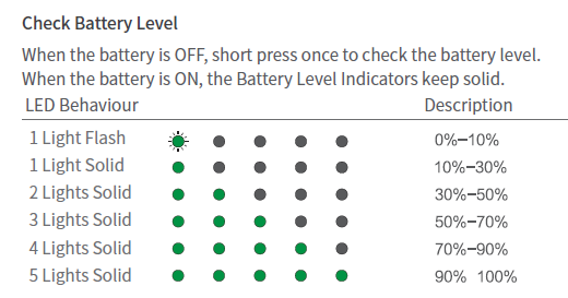
- During operation, please try not to over drain the battery. For practical use, make sure more than 2 lights illuminated green in minimal (i.e., 30%).

- During operation, avoid the battery temperature exceeding 70 degrees for continuous operation. Continuous high temperature operation will shorten the life span of the battery, and in serious cases, it will lead to smoke, explosion, etc.;
Completion of Work
- Do not plug and unplug the battery when the battery is turned on, otherwise the plug interface will ignite and damage the battery plug.
- After each sortie operation, the battery shall be charged in time to avoid over-discharge.
- If it needs to be stored for a long time, the battery needs to be charged and discharged every 90 days to maintain the health of battery cell.
- Please use the standard charger provided by XAG for charging. The customer shall be responsible for battery accidents, flight faults and other problems caused by charging with a charger not provided by XAG.
- The battery is flammable and explosive. Please do not sit on the battery, place heavy objects above the battery or squeeze the battery.
- Please keep away from inflammables, explosives, or gases when charging.
Properly Dispose of Batteries
- It is not recommended to send the battery back to the factory in case of fire, smoking, water soaking, deformation of electric core and other faults, and the battery shall be scrapped in a timely manner. The treatment method is to completely soak the battery with saline water for more than 72 hours (pour 250g salt every 10 liters of water) and ensure that the battery is completely discharged before drying and scrapping.
- When soaking in saline water, it shall be placed in an open outdoor place, and there shall be no flammable, explosive and other dangerous goods around.
- When discarding batteries, do not use metal or conductive containers to soak batteries.
- When discarding the battery, be sure to completely submerge the battery with saline water. Failure to completely submerge the battery will cause the battery to be unable to complete discharge.
- When discarding batteries, please abide by local laws and regulations. Do not arbitrarily discard batteries to jointly protect the natural environment.
Battery Tool Kit
Software update
Please download the battery tool kit, download link: please refer to Appendix II
XAG battery tool kit is displayed in Chinese by default. Before use, we need to change this software to English and update to the latest version.
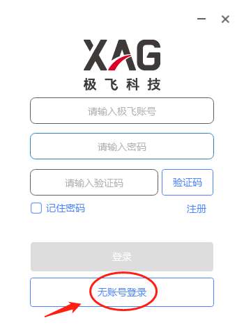
Open the battery tool kit software.

Login without account (无账号登录)
Update software to the latest version. Make sure your computer have access to internet
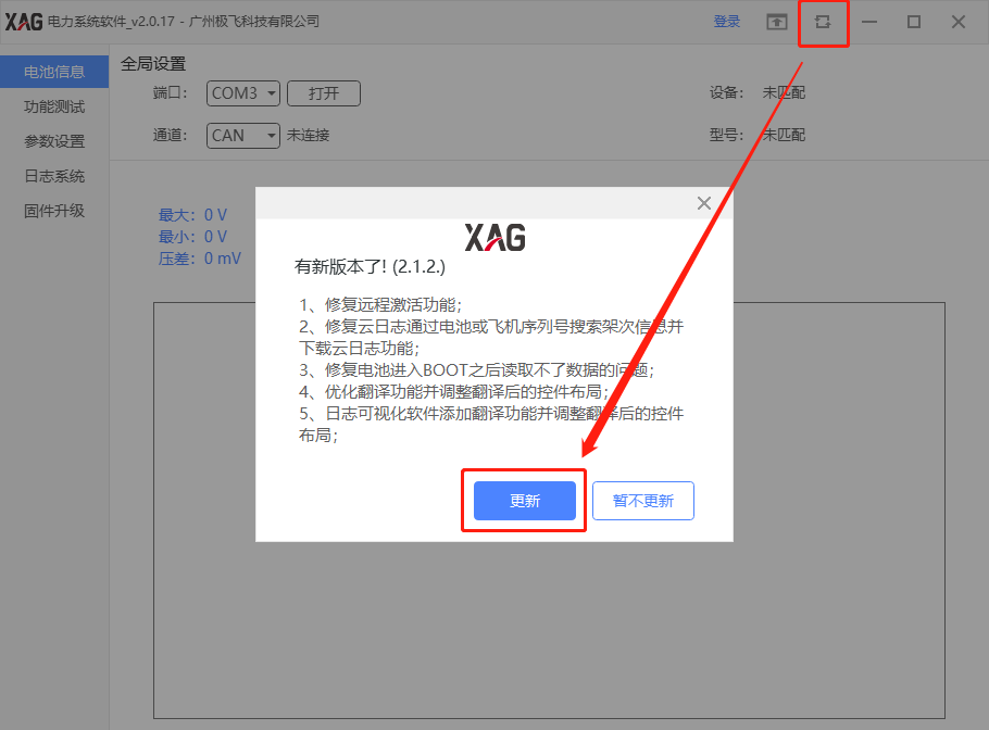
Depending on the software version, some users many see the different views.
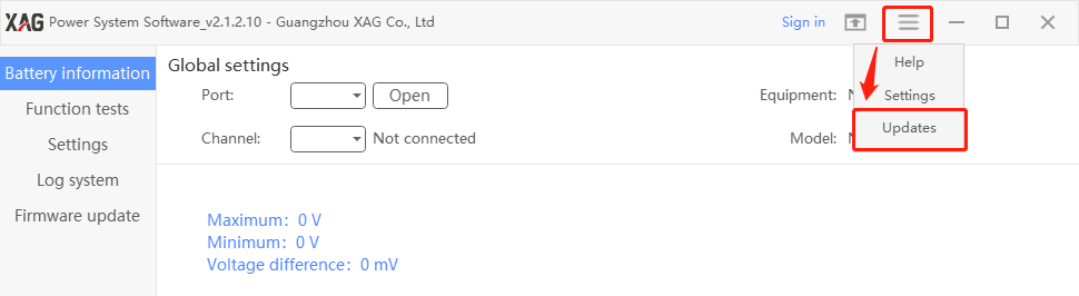
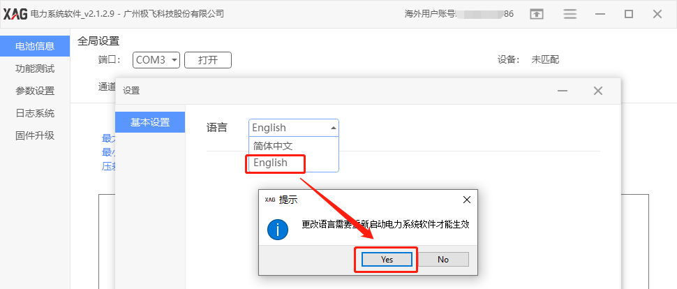
Language Change
After update, login without account again, and go to setting (设置)
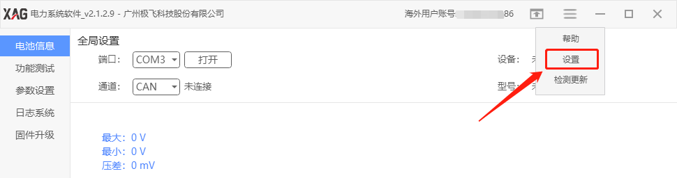
Change language (语言)to English
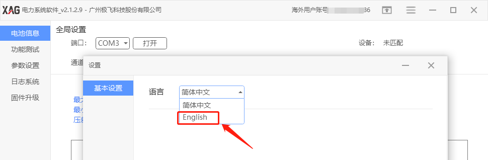
Press Yes to Confirm
Register or Login account
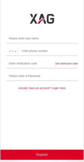
Register account
If you have an account, you can ignore this step.
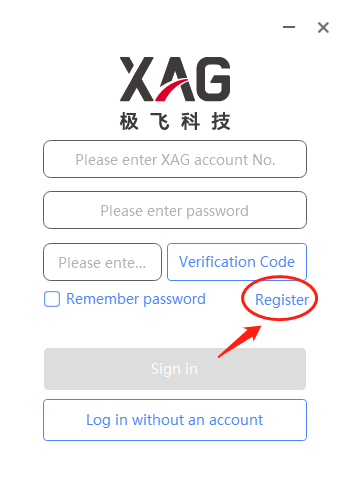
Login account
Input account ID and password, get verification code. Press sign in.

Hardware Setup
Preparation
|
Battery tool part number: 09-013-00001 If you don’t have this tool kit, please ask your sale representative. |
 |
|
B13960 cable adapter: 05-002-01152 If you don’t have this tool kit, please ask your sale representative. |
 |
Tool Setup
Connect your batter tool kit to laptop and B13960S battery. Make sure your battery tool kit software is running on your laptop.
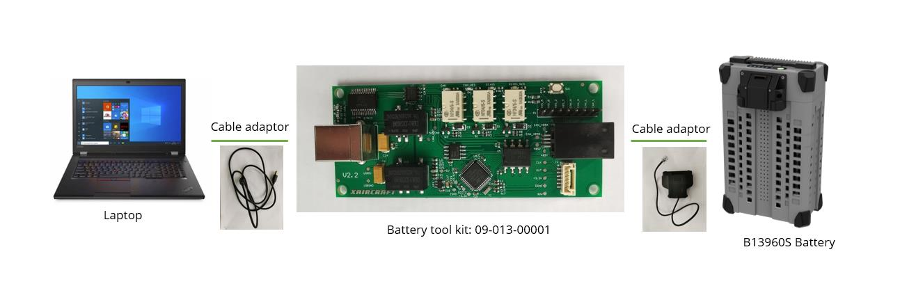
Make sure the cable adaptors are well connected.


Make sure that the “CAN_RES” light must illuminate in green. If not, please press the channel switch button to select “CAN_RES” channel.


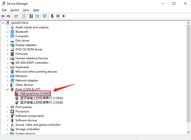
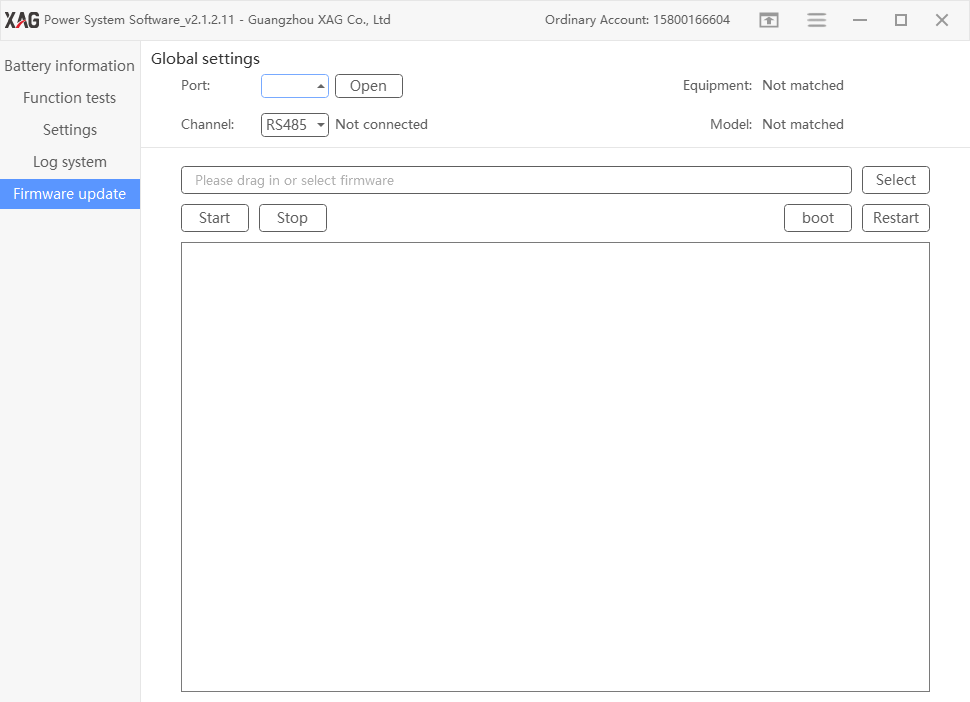
On laptop, go to device manager to check the available COM port
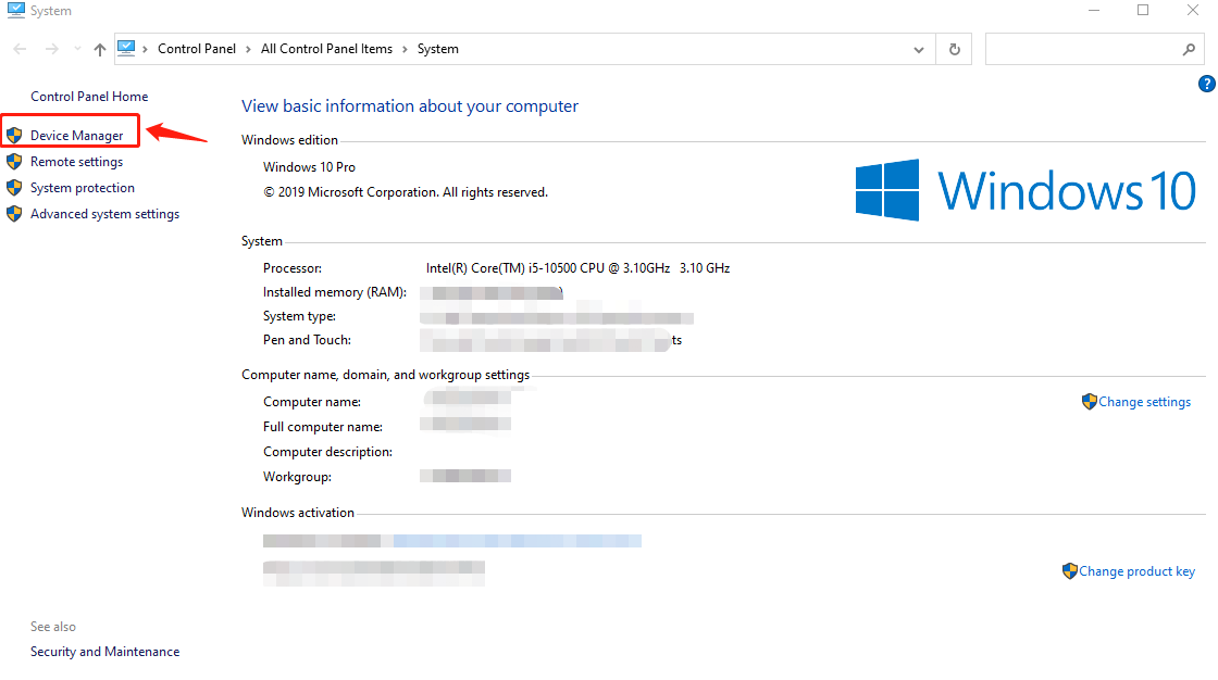
From here, we can know that the available COM port is COM7
Select Port 7 and Channel CAN under Global setting
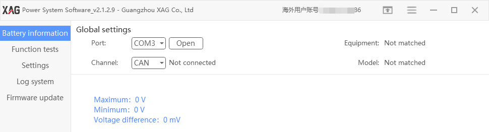
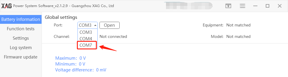
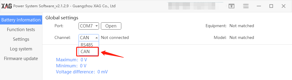
Press “Open”
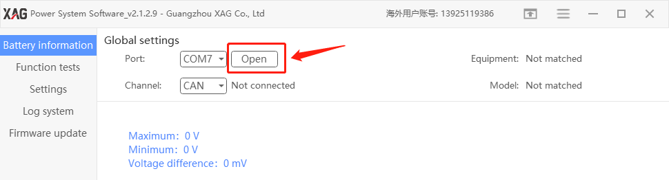
Make sure channel status display in “Connected”
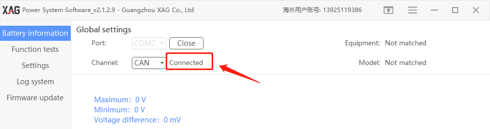
Turn on your battery B13960S
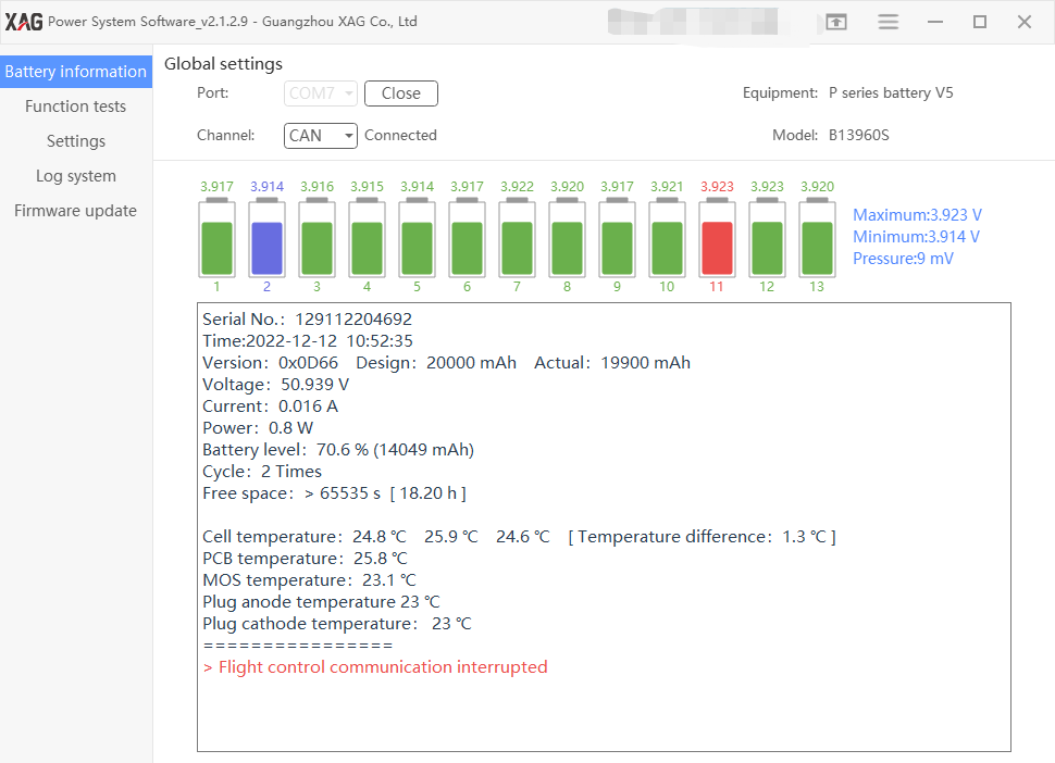
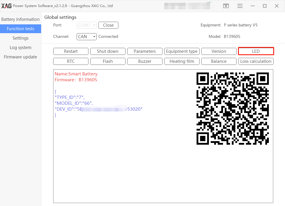
Once connected, check the battery tool kit software on laptop, you shall be able to see the following.
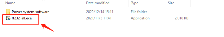
If it does not work, please install the driver ft232_all.exe, download link please refer to Appendix II.
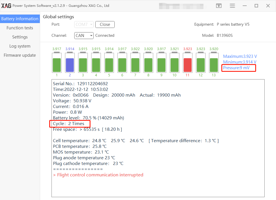
Battery Information
Check if the pressure difference is below 30mV.
In this case, the pressure difference is 9mV, which is good.
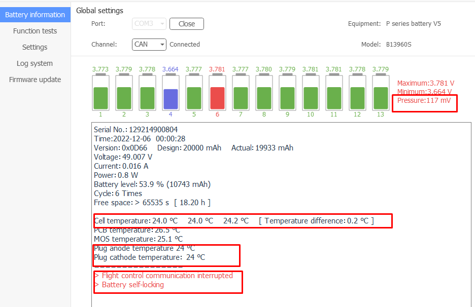
The below example shows the pressure difference is 117mV, which is not good. Please discharge and charge the battery twice and test again.
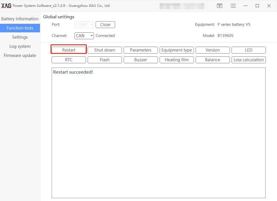
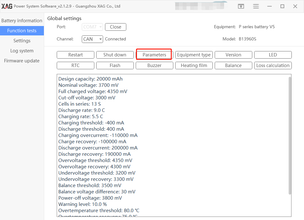
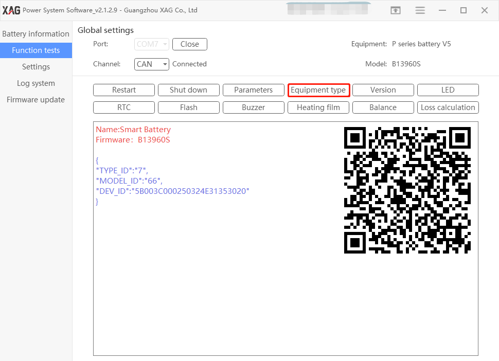
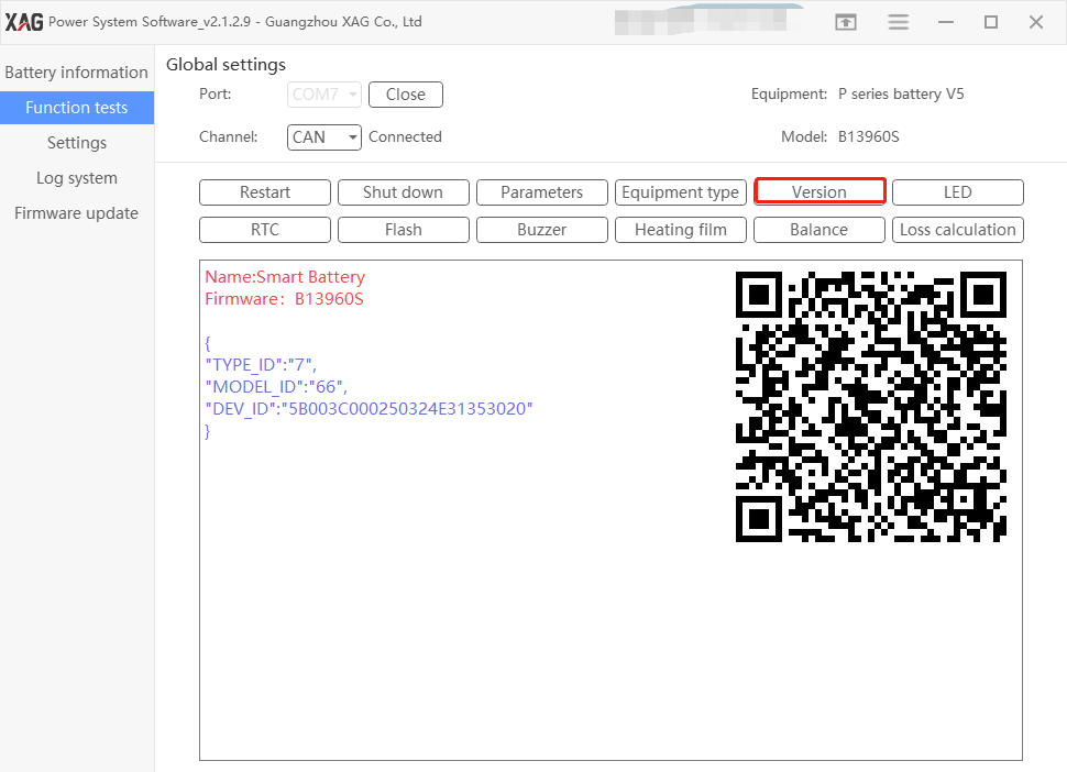
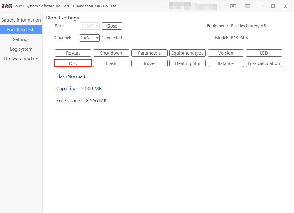
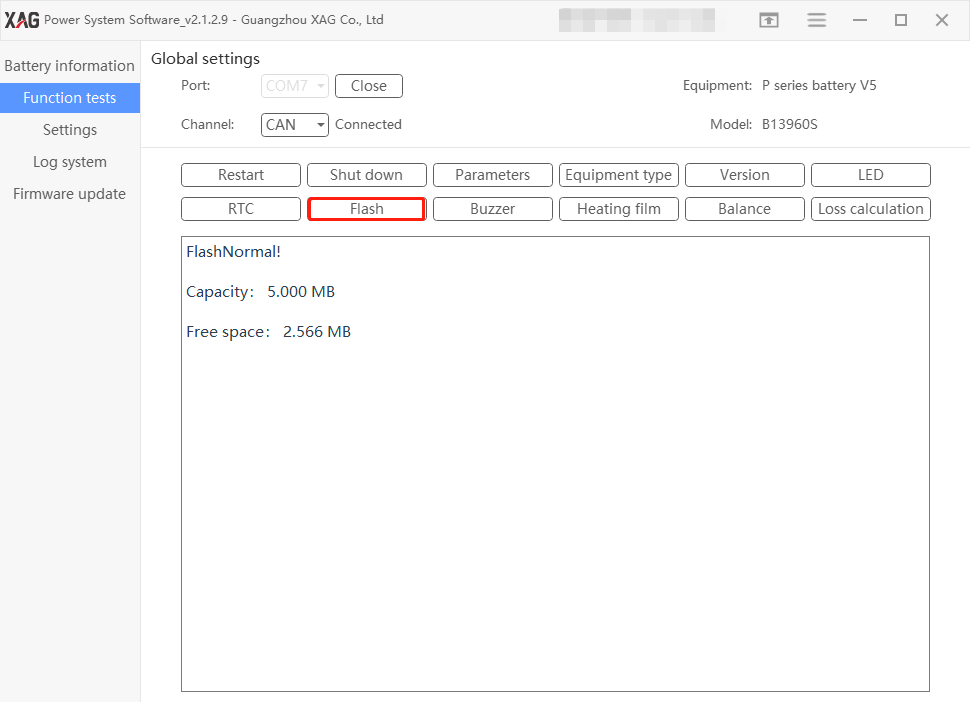
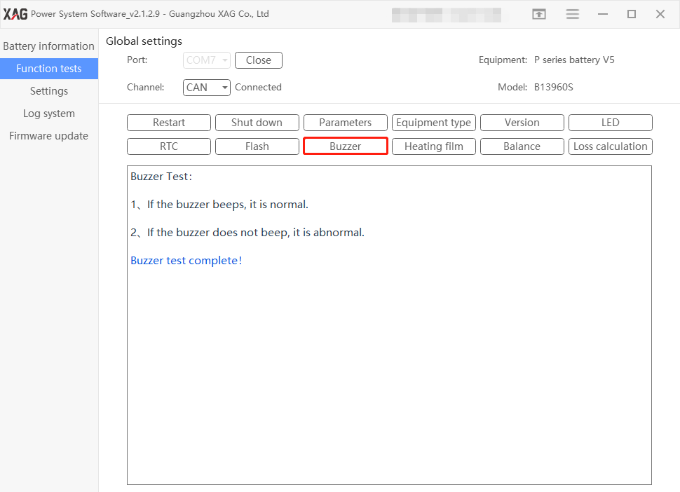
Function Tests
Restart
Parameter
Equipment Type
Version
LED
RTC
Flash
Buzzer
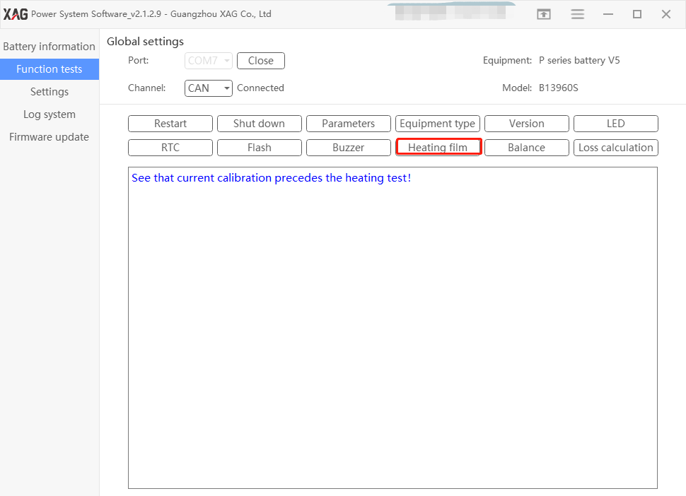
Heating Film
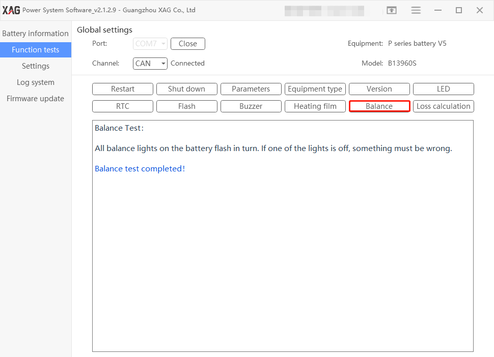
Balance
These balance lights are displayed in mainboard.
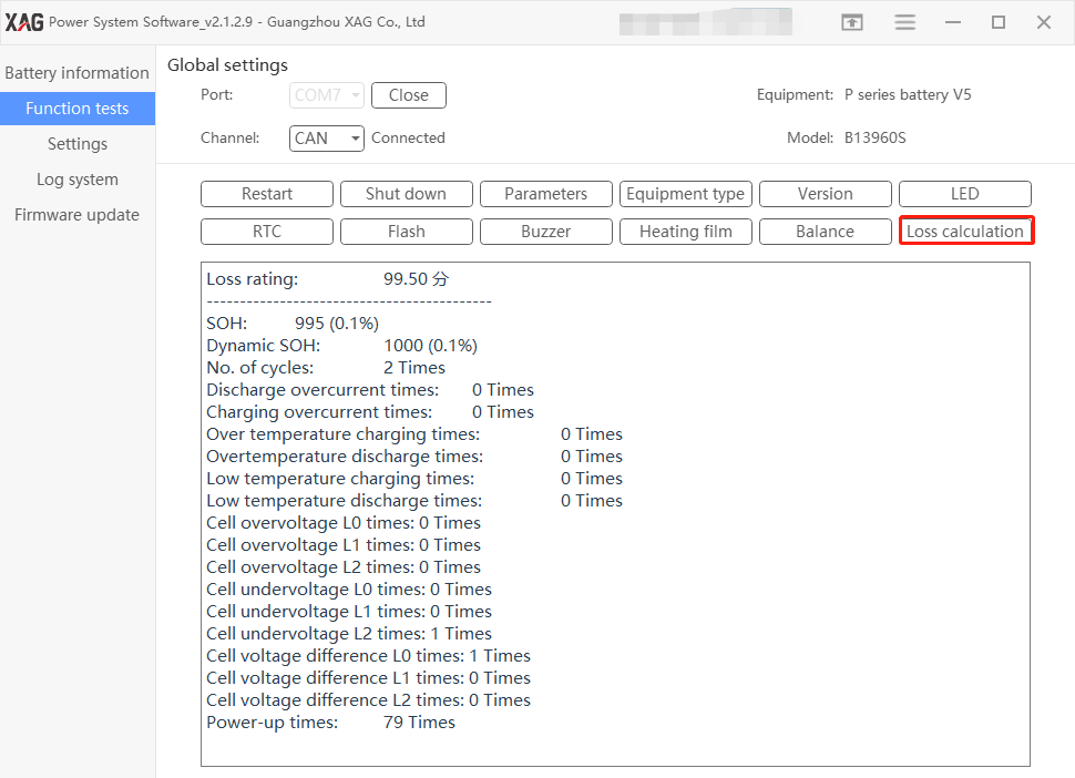
Loss Calibration
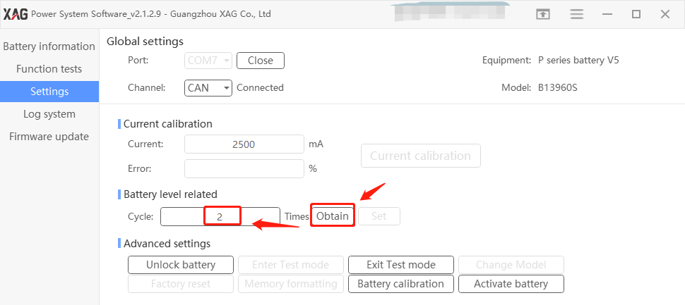
Obtain cycles
User can find out the exact number of cycles used. The cycle is calculated through the existing battery log stored in mainboard.
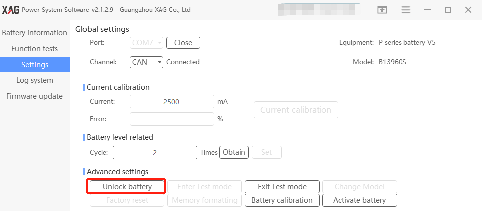
Unlock Battery
Faulty Lock
Battery can be locked if abnormal charge or discharge happens. In this case, there are two methods to unlock the battery.
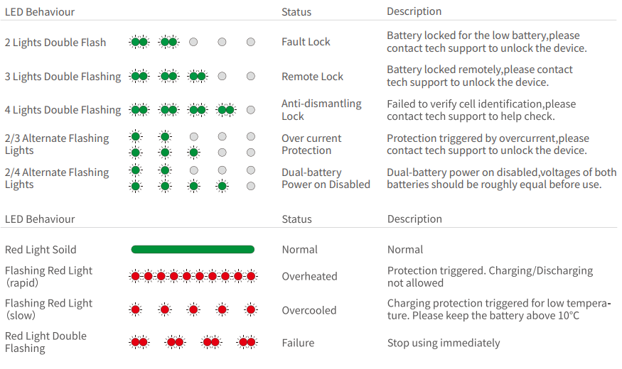
Led indication: Two leds of the battery level indicators double flash, battery cannot be used.
Unlock Method 1: Remote unlock
Requirement: An UAV can get online via sim card or RCN mode with internet access. Procedure:
- Put the locked battery in the UAV and turn on, wait until it is online.
- Contact the tech support in XAG, provide the SNs of the battery and the UAV to unlock the battery remotely.
Note: Authorized account which can see and perform “Remote operation” in the battery tool software, can perform remote unlock by itself with the tool.
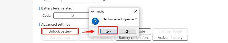
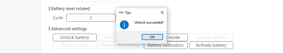
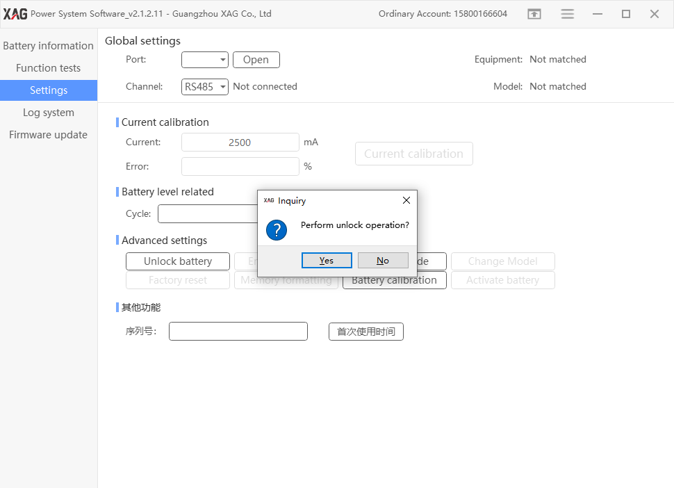
Unlock Method 2: Manual unlock
Requirement: battery tool kit and software Procedure:
- Connect the battery to the battery tool and PC, open the software in the PC
- Unlock the battery by step by step as following:
Cloud Lock
Batteries purchased from non-official overseas distributors will be locked due to geo-fence mechanism, which is called “cloud lock”. In this case, only remote unlock can be performed.
Led indication: three leds of the battery level indicators double flash, battery cannot be used.
Unlock Method: Remote Unlock
Requirement:
1. Authorization from the sales representative.
2 an UAV which can get online via sim card or RCN mode with internet access
Procedure:
- Make a claim to XAG sales representative who will authorize the back-end technical support to disable “Cloud lock”.
- Put the locked battery in the UAV and turn on, wait until it is online.
- Contact the tech support to unlock the battery remotely.
Note: Authorized account which can see and perform “Remote operation” in the battery tool software, can perform remote unlock by itself with the tool.
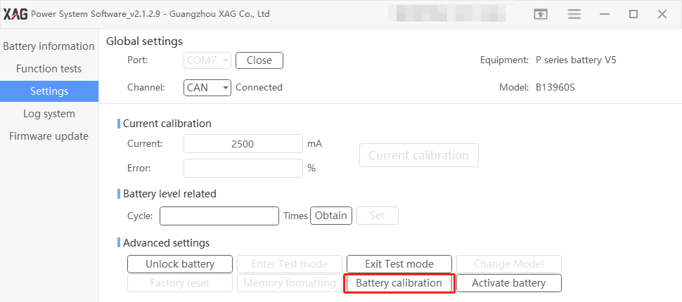
Battery calibration
After the replacement of mainboard or lithium cell, the battery reading could be inaccurate. In this case, users can do battery calibration.
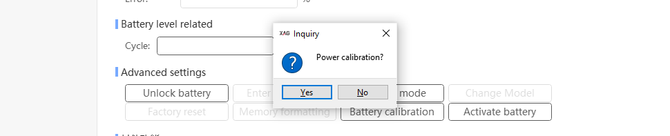

Activate Battery
When the battery head or other parts are replaced, you need to activate the battery.
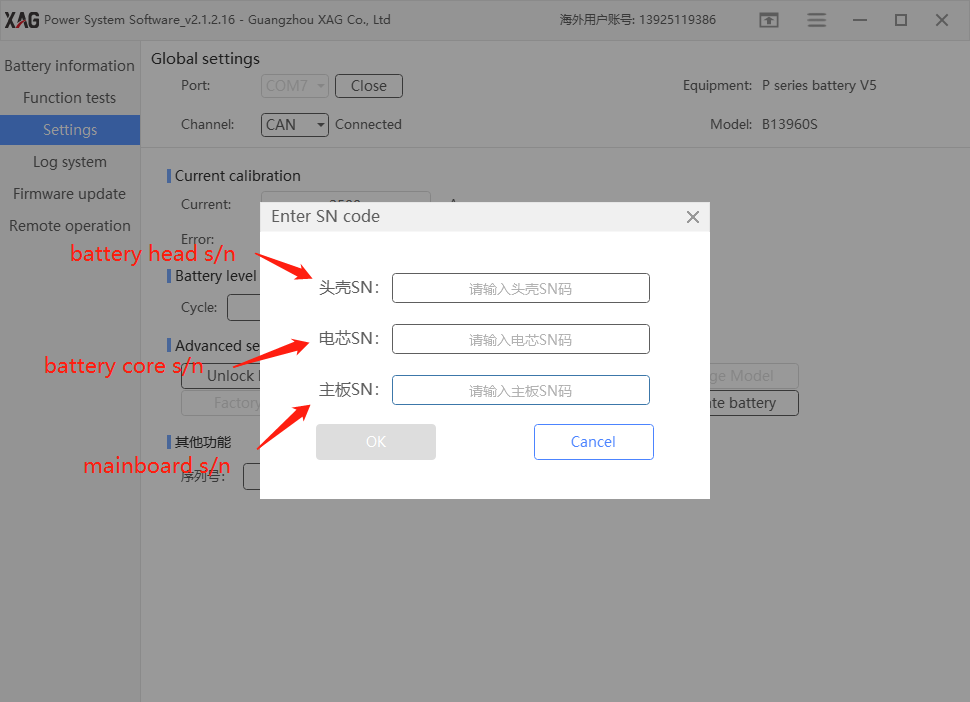
Procedure
- Make a claim with the XAG technical support team.
- Provide XAG technical support three s/n (the old battery head s/n, the new battery head s/n, the battery cell s/n, new mainboard s/n)
- Wait for the technical support to recombine the SNs of battery parts from the backend server
- Connect laptop to internet
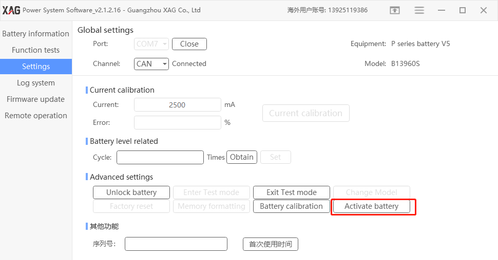
- Open battery tool software
- Connect battery to the battery tool software
- Go to setting, activate battery, fill out the information and press OK
Log system
Press “search index”
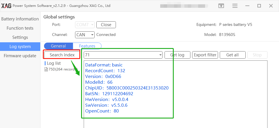
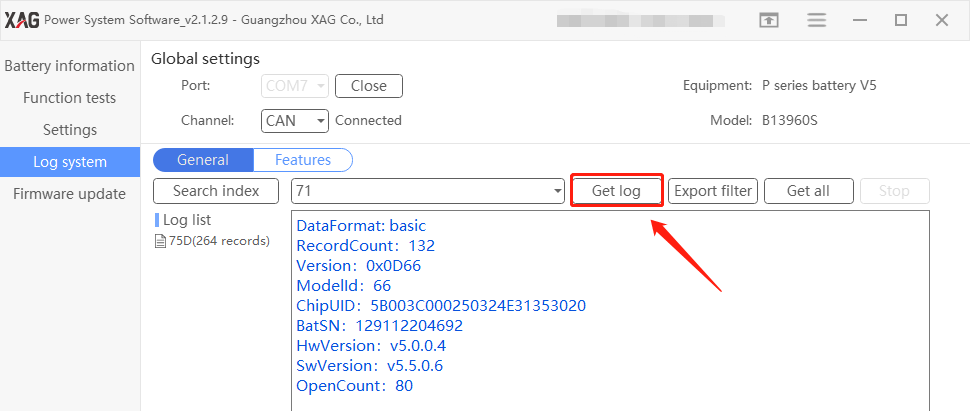
Then press log list and get log
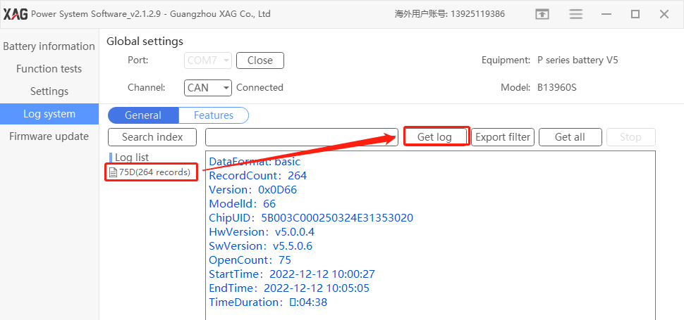
Get log
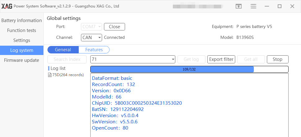
Wait for log exporting
Log is saved to the below path.
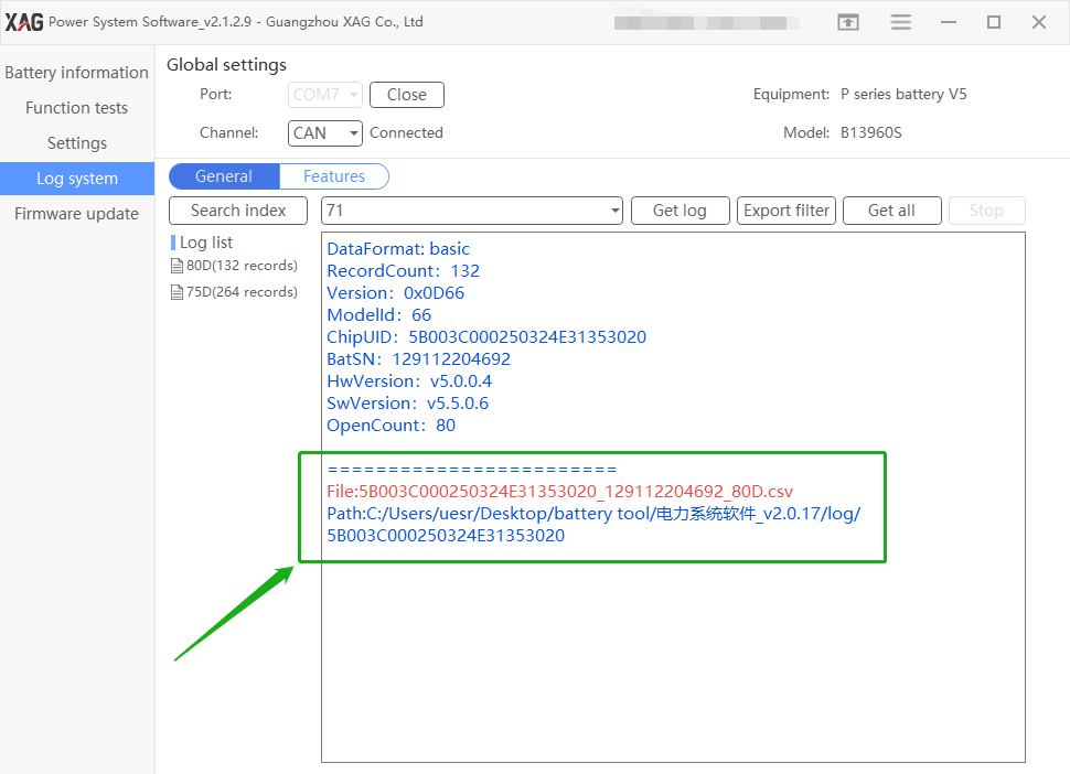
Forward the log to XAG technical support staff
Firmware Update
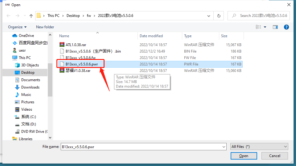
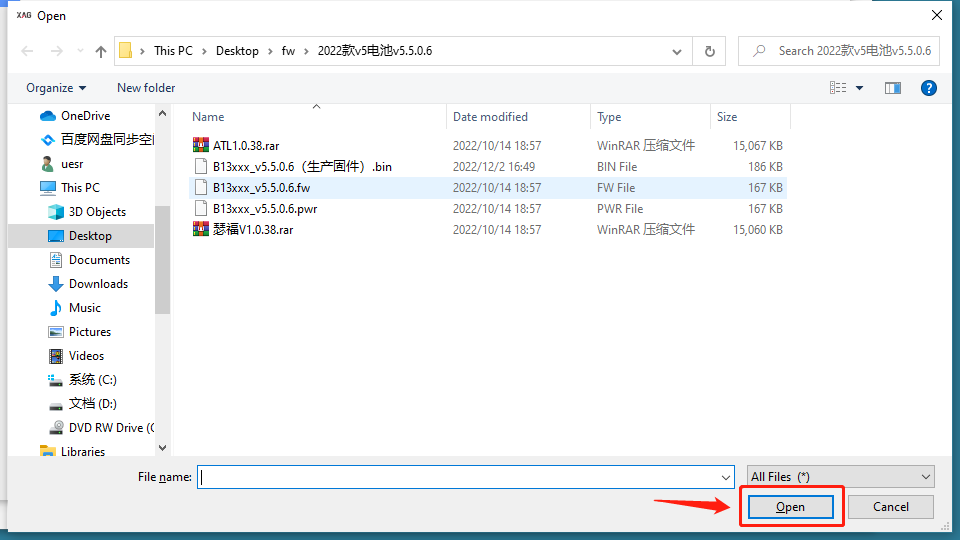
Select the firmware file
Please download battery firmware (2022 款 v5 电池 v5.5.0.6 ) , please refer to appendix II
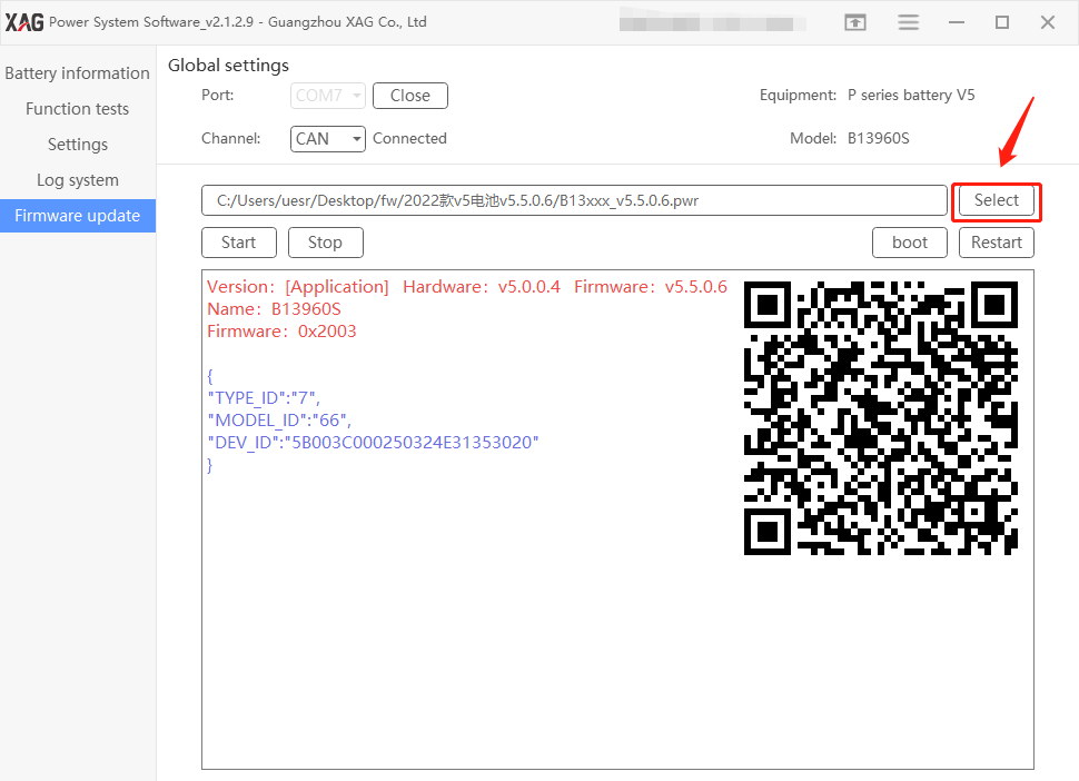
Choose the battery firmware file
Press start and Yes
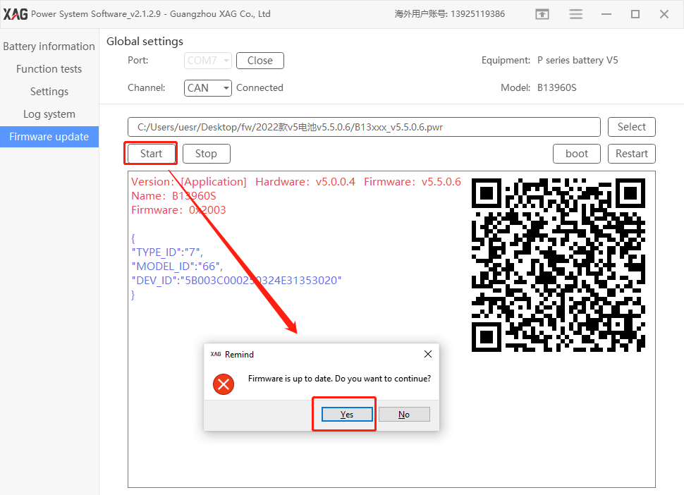
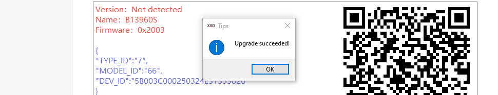
Wait for the update completed
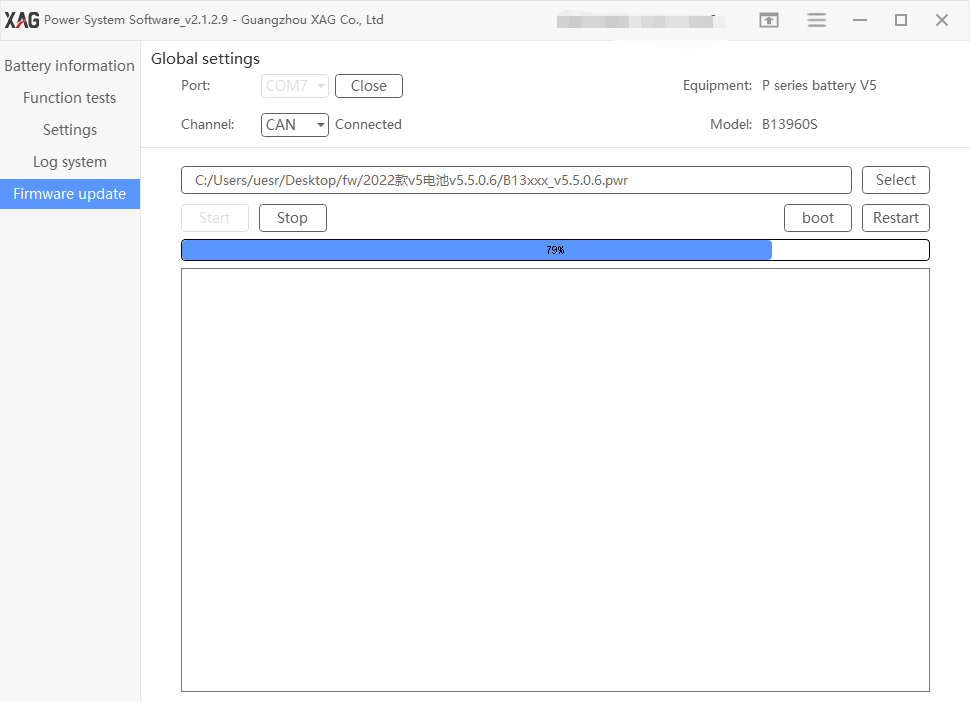
Update completed
Troubleshooting and Maintenance
Case Analysis
Troubleshooting 1. The power button does not respond
Troubleshooting method: if the battery does not start, the indicator light does not light up by pressing the start button. If the indicator light lights up normally by pressing the start button, the battery will not enter the start state or the battery will automatically shut down immediately after entering the start state.
1. All indicators do not light up when pressing the start button
- Use a multimeter to measure whether the total voltage of the battery cell is above 38V, and judge whether cells problem causes the fault. If it is not the cell’s fault, then need to replace the mainboard.
- If the fuse is in poor condition, adjust the multimeter to the buzzer gear, connect the probe to the metal parts at both ends of the fuse, and the buzzer of the multimeter will ring. If the number is 0, it means it is normal; otherwise, it is in poor condition.
- When the connecting wire of the battery cell is disconnected, use the buzzer gear of the multimeter to test whether the power on key is normal (under normal circumstances, press the power button, use the multimeter to measure the value of two pin groups on the same side, which shall be close to 0 Ohm, or measure the resistance of SW and Vin test points, which shall be 0 Ohm, otherwise the power button is abnormal); At the same time, check whether the mainboard is corroded or burned by liquid.
- Check whether the mainboard power supply is normal (press the power-on key on the mainboard and use a multimeter to measure whether there is 3.3V voltage between 3V3 output by the mainboard power circuit and GND test point, otherwise the mainboard is abnormal);
2. Press the power on button, the indicator light is normally on, the battery does not enter the power- up state or the battery automatically shuts down immediately after entering the power-up state
- If the indicator light turns on after pressing the power on button, it indicates that the mainboard supplies power and the power on circuit is basically normal. Check whether the battery has load and whether the load communicates with the battery mainboard normally.
- Check whether the metal contact of the charging plug is aged and corroded by the liquid inlet, resulting in abnormal communication between the load and the battery mainboard. Replace battery plug for detection.
- Check whether there is an open circuit and loose contact between battery plug and connecting wire of mainboard.
- If the mainboard circuit is abnormal, the cross-testing method can be used to detect the mainboard.
Troubleshooting 2. Two battery level lights are flashing and the power light(red) double flashing
Troubleshooting methods: The battery locking state is usually caused by abnormal use of the battery. The battery failure causes the battery protection locking. Use the battery tool to unlock. If unable to unlock the battery, analyze the following specific reasons:
- Connect the battery to the computer and use the battery tool software to check the battery information for abnormalities such as large pressure difference, large temperature difference and low cell voltage.
- Use the battery tool software to check the battery information data. If there are obvious abnormalities, replace the main board kit and battery cell respectively with the replacement method to judge the fault point (first, check whether the main board kit and battery cell have external deformation, liquid corrosion, component falling off and other poor appearance)
- If there are no obvious abnormalities in the battery data shown by the battery tool software, it is necessary to use the high-power electronic load instrument to test whether the battery is abnormal.
Troubleshooting 3. The battery light is running
Troubleshooting methods: Battery upgrade failed
- Turn on the battery, connect to the computer, and use the battery tool to upgrade
- The faulty battery can be plugged into the drone to start up, the firmware can be copied into the flight control for upgrading and troubleshooting, and the firmware can get from the XAG technicians.
Troubleshooting 4. charging fault
Troubleshooting methods:
- Check the charging port for dirt, deformation and poor communication caused by liquid inlet;
- Abnormal cells, such as abnormal cell temperature or differential pressure;
- The battery mainboard is filled with liquid, which is caused by circuit failure (troubleshooting by replacement method);
- If the battery is locked, contact XAG technicians to unlock it or use the battery tool;
- If the temperature of the newly flown battery exceeds the set value, the motherboard will protect the battery and prohibit charging. It is necessary to cool the battery in time.
Troubleshooting 5. Battery lock
Troubleshooting methods: The battery lock is generally locked when the power is too low and can only be used after unlocking.
- Contact XAG technicians to unlock it;
- Use the battery tool to unlock it with the computer
- The battery is locked due to poor battery cell or defected motherboard. At this time, it cannot be unlocked successfully
Troubleshooting6. Power on after the battery is plugged in
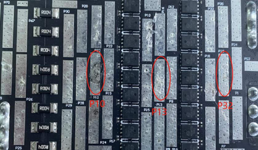
Troubleshooting methods: There is output voltage when the battery is plugged into the drone, it is normally the MOS tube of the power board breaks down to form a path. If the mainboard circuit control fails, check whether the power board MOS tube is burned, and determine the cause of the fault through appearance.
- Use a multimeter to measure whether the resistance values of P13 and P32 are normal. If the resistance value is 0, it indicates that the MOS tube of this path is faulty (or replace the mainboard for detection)
- Use a multimeter to measure whether the resistance values of P13 and P10 are normal. If the resistance value is 0, it indicates that the MOS tube of this path is faulty (or replace the mainboard for detection)
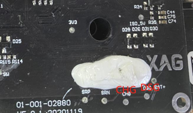
3. Measure the CHG and DSG test points on the mainboard without power-on. There should be no voltage. If there is voltage, the mainboard is faulty (or replace the mainboard for detection);
Troubleshooting 7. Abnormal temperature sensor
Troubleshooting methods:
- NTC resistance in the cell is abnormal, replace the cell.
- Main board liquid inlet corrosion or poor detection circuit.
- Loose connection terminal or poor contact.
Troubleshooting 8. Unable to unlock the battery
Troubleshooting methods: When the battery cannot be unlocked with the battery software tool
- Replace the mainboard for detection due to liquid corrosion and abnormal circuit.
- The battery cell is abnormal and large voltage difference, replace the battery cell for detection.
Troubleshooting 9. Battery plug temperature abnormal
Troubleshooting methods:
- Check whether the battery plug has such appearance problems as liquid inlet corrosion, melting head and serious wear. Or replace the battery plug for detection.
- The mainboard is in poor condition. Connect the temperature sensor in the battery plug to the mainboard detection circuit. Check whether the detection circuit works abnormally due to damaged components.
Troubleshooting 10. Four battery level light are flashing, and the battery cannot be activated
Trouble shooting methods: The battery cannot be activated with the battery tool after replacing the mainboard or cell
- Upgrade the battery's firmware to the latest and then use the power system software to activate.
- Check whether the computer network and battery tool communication are normal.
- Check the mainboard and the appearance of cell’s connecting wire or re-plug it.
- Replace the mainboard or battery cell
Troubleshooting 11. Battery alarm description on APP during flight
Troubleshooting methods:
Low voltage of battery cell
If the single voltage is lower than 3.2V, alarm will be given, and it is required to return for charging in time.
High discharging current
When the battery detection current exceeds the set value, an error will be reported; It can be checked as follows:
- Check whether the propeller is correctly installed, whether each propeller is deformed or damaged, and if there is no obvious deformation, test by replacing the propeller.
- Check whether the motor is normal, whether the motor base is horizontal, whether the boom and its fixing parts are deformed, and whether the propeller plane is in the right angle.
- Check whether the voltage of each battery cell is unbalanced and whether the battery power is sufficient.
- Reduce dosage in plateau areas
- Reduce the density of dosage
The temperature sensor of battery cell is abnormal
- NTC of battery cell is abnormal
- Mainboard is abnormal
The plug not secured
- The battery is not plugged in or the battery plug is poor;
- The battery tail plug aging
BMS abnormal
The plug connecting the battery cell and the mainboard is loose or the BMS circuit is faulty;
Battery cell abnormal
The load voltage difference of the battery cell caused by cell attenuation is large.
Battery discharge
The battery will be locked when the single voltage of the battery is lower than 3.1V.
Inspection after repair or maintenance
Appearance inspection
- Confirm that all components of the product are installed correctly
- Parts shall be assembled in place without missing assembly and there is no deformation in appearance.
- Shake the product slightly and there shall be no abnormal sound inside.
Function inspection
- Use the "Power System Software" to connect the battery to check whether the battery information (differential pressure, temperature, firmware version) is normal.
- If the mainboard or battery cell is replaced, calibrate the electric quantity.
- If the firmware version is too low and needs to be upgraded to the latest firmware for use
- Charge and discharge test after the above items are normal (check whether the battery can be fully charged and whether the discharge is normal)
Visual inspection
If you see battery bulge, deformation, chemicals leakage or physical damage, please stop using the battery immediately and contact Xcare team.


You can soak the battery into salt water to eliminate the risk of fire.
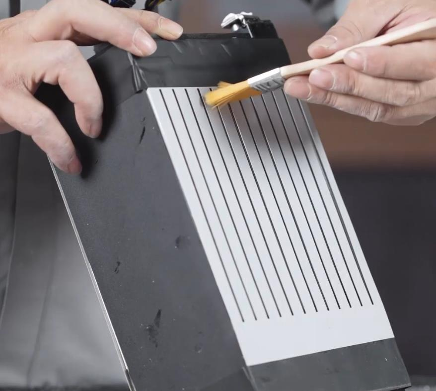
As the battery case has holes for cooling, please inspect if dust or impurities go inside the battery case
Cleaning
Please remove the battery case and clean the lithium pack if necessary.
Storage
This storage guide can apply to the products, including B13960S smart battery, XRTK4 portable station battery bar, ACS2 remote controller battery, UPS backup battery.
Lithium-ion battery are fire hazards, so How should we store the lithium batteries?
In general, Lithium-ion batteries (Li-ion) should not be stored for longer periods of time, either uncharged or fully charged. The best storage method, as determined by extensive experimentation, is to store them at a low temperature, not below 0°C, at 40% to 50% capacity. Storage at 5°C to 15°C is optimal. Since lithium batteries self-discharge, it is recommended that they must be recharged every 12 months.
We can further divide it into short-term storage and long-term storage.
Short-terms storage: Store the battery in a dry place with no corresive gases and a wet temperature between 10℃-30℃, higher or lower temperature will cause metal parts of the battery to rust or the battery to leak.
Long-term storage: As long term storage will cause the battery activity passivation and accelerate the self- discharge rate, the ambient temperature should preferably be between 10 ℃-30 ℃, in addition, it is necessary to do a charge/discharge cycle every 3 months to maintain its activity and recovery performance.
For safety concerns, please do not charge the battery full but maximum 80%. Charge 60% to 70% of the battery charge and place in a dry environment. Cooler temperatures and less charge are conducive to maintaining the life of the battery, but too little charge cannot be, because the battery will be self-discharge in storage, once the battery slowly run out of power, it will seriously shorten the battery life.
Some may ask, should the battery be removed from the device when not in use for a long period of time?
Yes. There is also a small current flowing through the shutdown device, causing a complete discharge, which can damage the battery over time, and in the worst case scenario, destroy the device along with it.
 To help you understand better about the storage of lithium batteries, we’ve summarized a list of prohibitions.
- Do not charge the battery under fire or extreme heat. Do not use or store the battery near a heat source (such as a fire or heater). If the battery leaks or emits a peculiar smell, immediately move it away from the open flame.
- When the battery swells up, leaks, etc., stop using it immediately
- Do not put the battery in water or get it wet
- Do not throw the battery into the fire or heat the battery
- Do not connect the battery directly to a wall socket or car cigarette lighter socket
- Do not short-circuit the positive and negative poles of the battery with wires or other metal objects. It is forbidden to transport or store the battery with necklaces, hairpins or other metal objects.
- Do not knock, acupuncture, step on, modify, or expose the battery to the sun, and do not place the battery in a microwave or high-voltage environment.
- Do not hit, throw, or subject the battery to mechanical shock
- Use a regular matching lithium battery charger to charge the battery, do not use inferior or other types of battery chargers to charge the lithium battery.
- Do not disassemble the battery in any way
- Do not mix the battery with metal objects, lest the metal objects touch the positive and negative electrodes of the battery, causing a short circuit, damaging the battery or even causing danger.
- Do not use with primary batteries (such as dry batteries) or batteries with different capacities, models, and varieties.
- Do not use the battery if it emits peculiar smell, heat, deformation, discoloration or any other abnormal phenomenon. If the battery is in use or charging, it should be removed from the electrical appliance or the charger immediately and stop using it.
- In the transportation process, pay attention to moisture-proof, moisture-proof, avoid squeezing, collision, etc., to avoid battery damage.
- Do not use or place the battery under high temperature (in the hot sun or in a very hot car), otherwise it may cause the battery to overheat, catch fire or function failure, and shorten its life.
- Do not store in places with strong static electricity and strong magnetic fields, otherwise it is easy to damage the battery safety protection device and bring insecurity.
- If the battery emits peculiar smell, heat, discoloration, deformation, or any abnormality during use, storage, or charging, immediately remove the battery from the device or charger and stop using it.
- Discarded batteries should be covered with insulating paper to prevent fire and explosion.
Lithium battery Storage Checklist
Before storing, remove the battery from the device
Charge or discharge the battery to 3.8V (use the charger set in “storage mode” or use a voltmeter to check V).
Use insulating materials (such as plastic, electrical tape) to protect the battery terminal. Put the battery in a fireproof bag/container.
“Lithium-ion battery only” storage area Room temperature and no heat source Dry and well-ventilated place
Remove all combustible materials (wood, carpet, gasoline is prohibited, ceramic or cement surfaces are recommended).
There must be an ABC or water fire extinguisher nearby. And know its location
Emergency treatments
Thermal runaway begins when the heat generated within a battery exceeds the amount of heat that is dissipated to its surroundings
Scenario 1 —Temperature is high, but no fire
In case of smoke, turn off the power supply in time, let it cool naturally. During the cooling process, please observe whether the heating of the battery is relieved. If not, please put the battery in clean water for cooling.
Scenario 2 — Battery smoking
Take out the battery in time and put it in clean water for cooling (soaking).
Scenario 3 — The battery suddenly smokes during charging
If the battery suddenly smokes during charging, please cut off the main power supply of the charger immediately and remove the battery on the premise of ensuring the safety of personnel. If personnel cannot get close to the battery, please abandon the equipment, and directly use clean water jet or fire extinguisher to cool down and extinguish the fire.
Scenario 4 — The drone crashed in flight, resulting in battery smoke
Take out the battery on the premise of ensuring the safety of personnel. If personnel cannot get close to it, please abandon the equipment, and directly use a clean water jet or fire extinguisher to cool down and extinguish the fire. When it is determined that the battery temperature has decreased and there is no danger, proceed to the next step.
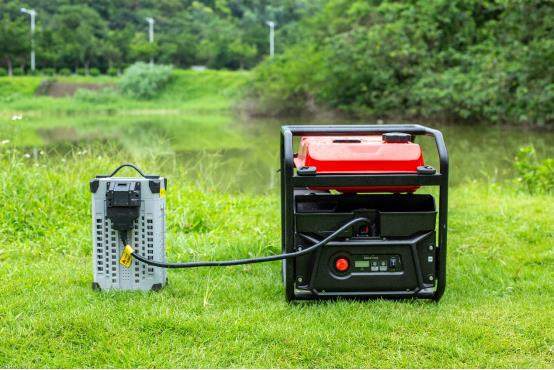
GC4000+ Auto Super Charger Station
Overview
Auto Super Charger Station is required to maintain and service after a certain period. During maintenance and service, make sure auto super charger station is turned off.
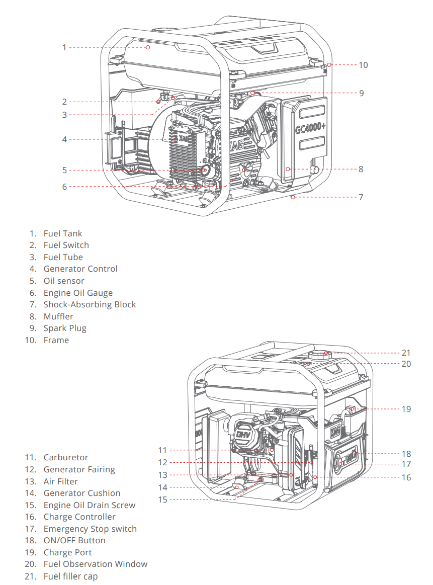
GC4000+ The Super Charger Station Maintenance Guide
|
Item |
Action |
Service Notes |
|
Engine Oil |
Inspect |
Inspect engine oil level every time before use |
|
|
Change |
The 1st service should be taken placed after 20 accumulated operation hours. The 2nd and the reset of service should be taken place every 50 hours accumulated operation hours. |
|
Air Filter |
Inspect |
Inspect air filter every time before use |
|
|
Clean |
Clean air filter for every 50 accumulated operation hours |
|
Spark plug |
Change |
Change for every 500 accumulated operation hours |
|
Air Valve |
Adjust |
Adjust air value for every 500 accumulated operation hours. You may ask help from engine technician. |
|
Oil Tank and filter |
Clean |
Clean the oil tank and its filter for every 2 years |
|
Oil tube |
Change |
Change if it’s worn out. |
In addition, if you are unsure of repair and maintain super charge station by yourself, you can feel free to take your super charge station to any motorcycle repair workshop or any workshop repairing engines.

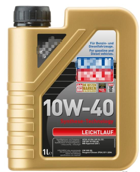
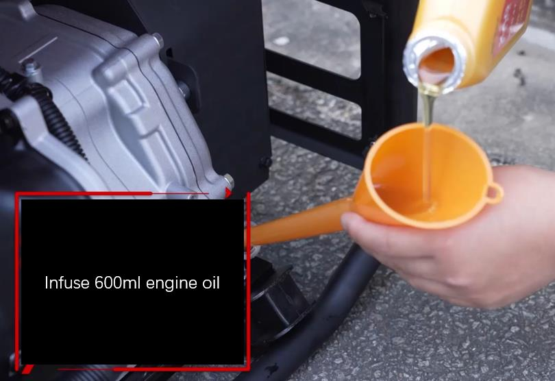
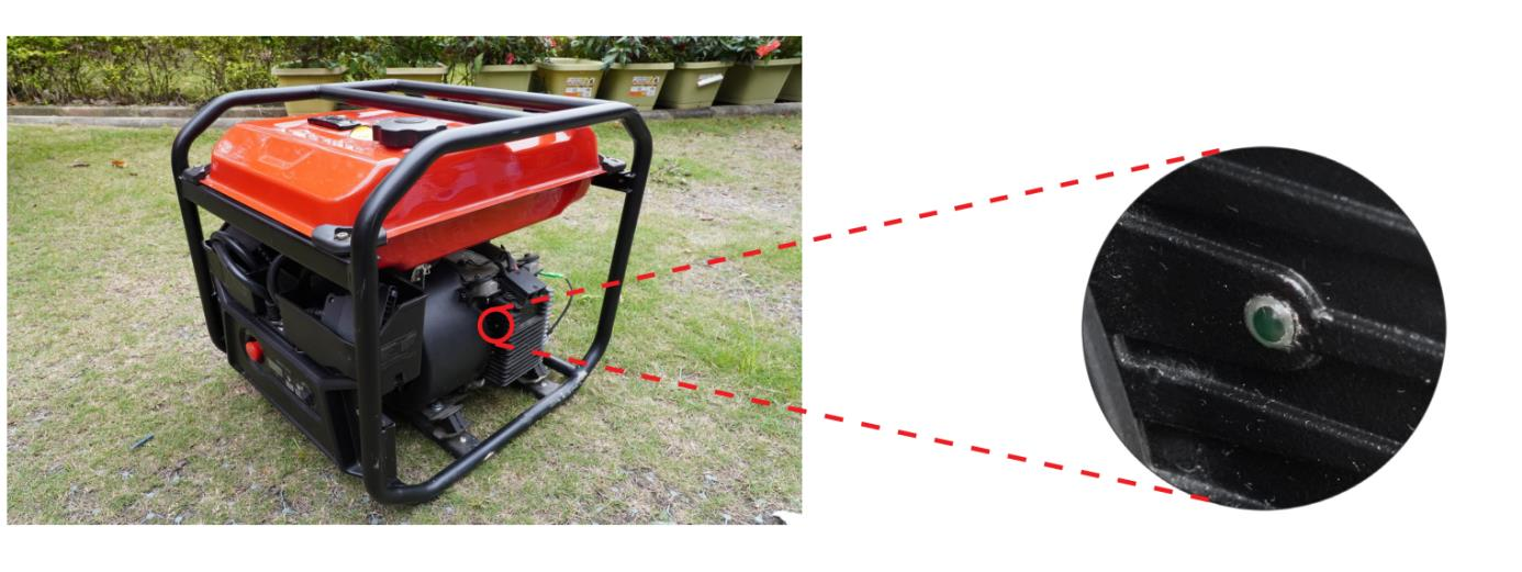
Oil Change
Please select 10W-40 engine oil
For each service, infuse 600ml engine oil.
Super charge station may be malfunction if infusion volume is not equal to 600ml.

The 1st service should be taken placed after 20 accumulated operation hours.
The 2nd and the reset of service should be taken place every 50 hours accumulated operation hours.
Inspect the remaining engine oil level

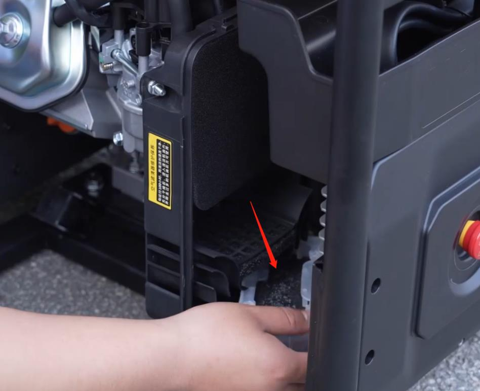
Clean Air Inlet Filter
Clean air inlet filter for every 50 accumulated operation hours
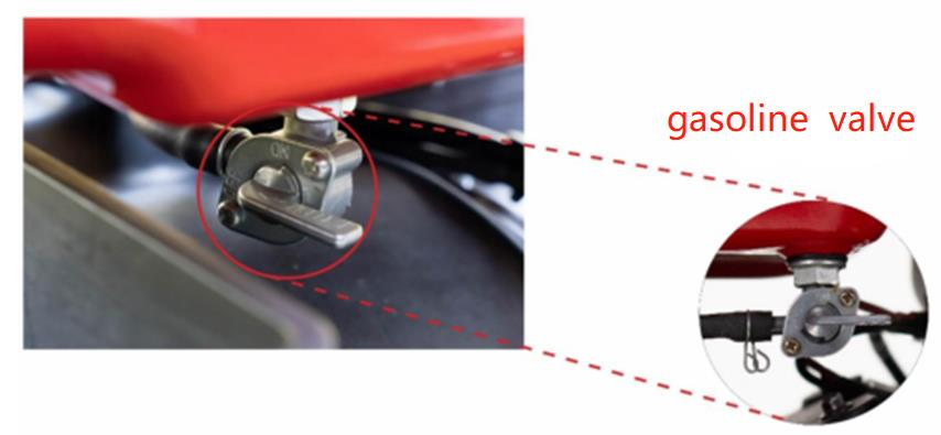
Inspect fuel system
- check if the fuel pipeline and replace it in time if it has been worn out.
- if not used for a long time, the fuel in the tank and pipeline needs to be drained.
- Close the gasoline valve, check the fuel tank, fuel tank cap, carburetor, fuel switch, etc., if there is any damage, leakage. please replace them immediately.
Inspect Spark plug
Every 500 hours of operation, the spark plugs need to be inspected. Pull out the high-pressure cap, use the sleeve to unscrew and check the spark plug, if there is an abnormal situation such as burning, it needs to be replaced by a specialist.

Inspect Air Valve
Every 500 hours of operation, a specialist adjusts the valve clearance.

Verification: Charge battery after service
Each time the maintenance is completed, a charge test is required to ensure that the charging function can be used normally.
Engine Controller Light Indicator
| Light indicator | Illustration |
 |
Engine controller has no calibration data |
 |
Engine malfunction, Fuse melt down, motor disconnected, motor phase loss, etc |
 |
Exceed maximum allowable current during startup. Hardware protection mode is enabled. |
 |
MOS high side short High side = the current travels from the supply through the MOS to the load and then to ground |
 |
MOS low side short Low side = MOS source to ground, drain to load, load to supply |
 |
Exceed maximum allowable current during startup. Software protection mode is enabled. |
 |
Voltage exceed +85V |
 |
Rectifier bridge open circuit or disconnected |
 |
Engine controllers overheat |
 |
No input signal or under work status |
When the GC4000+ is malfunctioned, please analyze the scenario according to both fault code and Engine controller light indicators.
GC4000+ Firmware Update
Online Method
Install smart battery B13960S in UAV
Open APP and update the battery and GC4000+ firmware.
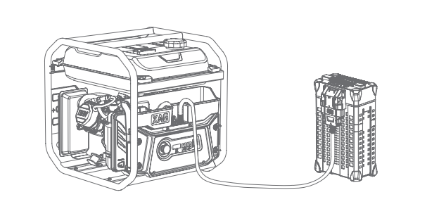
Please notice that GC4000+ firmware will be stored in smart battery. Connect battery to GC4000+
Turn on both battery and GC4000+. The GC4000+ firmware will be transferred from battery to GC4000+. Wait for a while until the firmware update is completed.
Offline Method
Copy the GC4000plus firmware file to UAV flight control
GC4000plus firmware (GC4000plus_v3.1.24) download link: please refer to Appendix I Install smart battery B13960S in UAV
Restart UAV
The FC will update GC4000+ firmware in B13960S after restart, please wait for a short while.Please notice that GC4000+ firmware will be stored in B13960S.
Connect battery to GC4000+
Turn on both battery and GC4000+. The GC4000+ firmware will be transferred from battery to GC4000+. Wait for a while until the firmware update is completed.
When shall user update GC4000+ firmware?
- Regular maintenance
- GC4000+ function abnormally
- GC4000+ online update failure; It keeps flashing red and green all the time, seem the firmware update but never complete. In this case, the GC4000+ need to update it again manually (Use offline method)
Troubleshooting
GC4000+ super charger is used to generate electricity for smart battery. It consumes gasoline fuel and is required to maintain after a certain period of time.
Fault code
| Fault Code | Photo | Illustration | Troubleshooting |
| E1 | 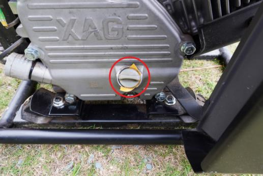 |
Low engine oil |
Add or replace engine oil |
| E2 | 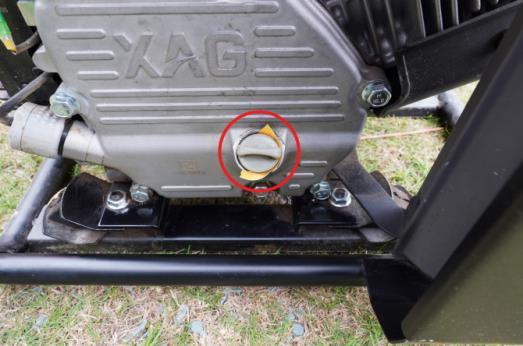 |
Service Required. |
After oil change, the repeatedly turn on/off button 3 times to remove the fault code. |
| E3 |
|
Control panel overheat |
Stop use for 10 minutes. Inspect if the control panel is loosened. |
 |
Control panel overheat |
Stop use for 10 minutes. Inspect if the charge controller is displaced. |
|
 |
Control panel overheat |
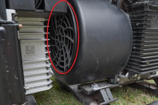
Stop use for 10 minutes. Inspect if the heat dissipation fan or motor air intake are blocked |
|
| E4 | 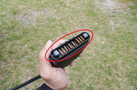 |
Exceed maximum current limit |
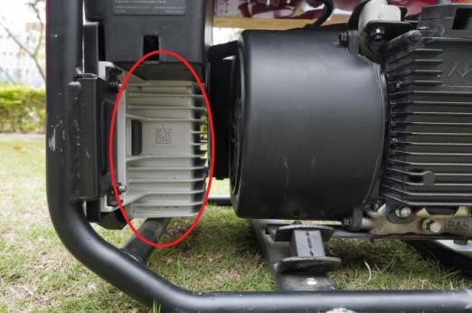
Clean the charge socket
Replace control panel |
| E5 |  |
Voltage exceed 86V during operation |
contact XAG technical support to export battery log, check whether the battery is under protection mode, which is caused by abnormal temperature, voltage, current, communication. |
|
Voltage exceed 96V during startup |
Adjust and turn the idle valve counterclockwise. |
||
| E7 | 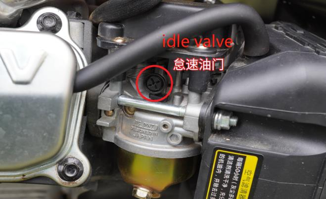 |
5 consecutive failures of startup |
Change engine oil Add gasoline Adjust and turn the idle valve clockwise. |
| E8 |  |
Control panel malfunction |
Replace a new control panel |
| E11 |  |
Battery communication failure |
Contact XAG technical support |
| E12 | 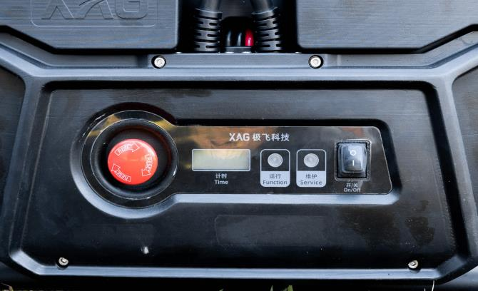 |
Control panel malfunction (current) |
Replace a new control panel |
| E13 |  |
Control panel malfunction (voltage) |
Gasoline quality is too bad. Please change gasoline.
Check if battery is in protection mode.
Replace a new control panel |