.png?height=120&name=Pegasus%20Robotics%20Logo%20-%20Portait%20(2).png)
Service and Maintenance
General UAV Maintenance program
Maintenance Inspection Cycle table
|
Maintenance Inspection Cycle Title |
Period |
Standard |
|
Start of Day Inspection |
Before each day’s flying |
Start of Day Inspection |
|
Pre-flight Check |
Before each flight |
Pre-flight Inspection |
|
Daily Post-Flight Clean |
After each day’s flying |
Daily Post-Flight Clean |
|
10 Hour Check |
Every 10 Hours |
10 Hour Check |
|
Battery |
100 charging cycles or 3 months, whichever is first |
1. Check whether the battery has swollen or misshapen. 2. Charge and discharge the battery at least once every 3 months to keep it in good condition. |
|
|
500 cycles |
Replace |
|
Auto Super Charge Station |
20h usage |
1. Visual inspection to check whether the charger has experienced any collision, and whether the charging cable connector is malfunctioning. 2. The Super Charger Station Maintenance Guide |
|
|
50h usage |
|
|
|
100h usage |
|
|
50 Hour / Monthly Inspection |
Every 50 flight hours or every months, whichever is first |
50 Hour / Monthly Inspection All Daily Pre-flight items All 10 Hour Items. |
|
12 Month Electrical System Overhaul |
12 months usage |
Replace all 12-month items due for replacement as per Lifed Items table. |
|
Spray Pump |
200h usage |
Replace |
|
Propellers |
100h usage |
Replace |
Lifed Items Reference
The following table specifies the recommended component life limits for components other than those specified in the Maintenance Inspection Cycle table
|
Item |
Period |
Standard |
|
Motors |
150h |
Replace if worn out or corrosion |
|
Motor base |
200h |
Replace if crack |
|
ESC |
300h |
Replace |
|
Propeller blade |
100h |
Replace if deformation |
|
Propeller clamp |
200h |
Replace if worn out |
|
Screw bolts on frame arm |
100h |
Replace if worn out or corrosion |
|
Aircraft cables/connectors |
100h |
Replace if worn out |
|
Main Frame |
400h |
Replace if crack |
|
Landing skid |
200h |
Replace if crack |
|
Spray nozzle |
200h |
Replace |
|
Spray pump |
200h |
Replace |
|
Spray disk |
100h |
Replace |
|
Spray solenoid valve |
100h |
Replace if corrosion |
|
Hose Connector |
200h |
Replace |
|
Hose |
100h |
Replace if worn out |
|
Filter Basket |
300h |
Replace if worn out |
|
Liquid Level sensor |
300h |
Replace |
|
Spreader motor |
200h |
Replace |
|
Feeder motor |
200h |
Replace |
|
Spreader disk |
200h |
Replace if worn out |
|
Spiral Feeder |
50h |
Replace if worn out |
|
Flight control |
12 months usage |
Replace if malfunction |
|
Cable hub |
12 months usage |
Replace if malfunction |
|
Radar |
12 months usage |
Replace if malfunction |
|
Terrain Module |
12 months usage |
Replace if malfunction |
|
Antenna |
6 months usage |
Replace if malfunction |
Attention: the above items are only for reference, please use it on your own risk.
XAG P100/P40/V40 Major Inspection Schedule
Make/Model: Serial Number/ FCSN:
|
Item |
Due |
This Inspection |
Next Due |
|
Date: |
|
|
|
|
Flights: |
|
|
|
|
Flight Hours: |
|
|
|
|
Module |
Daily Preflight |
10 Hour Check |
20 Hours Inspection |

Start of Day Inspection
The following inspection must be performed before flight each day:
- Clean and check propellers.
- Check propeller adaptor.
- Inspect Airframe.
- Inspect battery connector – ensure clean, dry, and free of defects.
- Sprinkler system atomization and nil leakage.
- Hose Connector condition and tightness.
- Hose not broken or worn.
- Check filter and liquid level gauge.
- Check Charging system.
An expanded and illustrated daily pre-flight inspection list is provided below.
|
Illustrated Start of Day Inspection |
|
|
Procedure |
Photo |
|
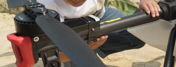
Clean and check propellers: Clean the propeller, hold the end of the propeller, lift gently and check whether the edges show any cracks. Check if the propeller is loose. Use an M5 screwdriver to tighten the propeller’s securing screws. Recommended torque: 20.0 kgf*cm. |
 |
|
Check Propeller adaptor: Rotate the propellers horizontally to the limit position of the propeller adapter and check whether the limit position is misshapen or broken. |
 |
|
Inspect Airframe: Check the aircraft landing brace, arms, main beams to ensure there are no deformities, cracks, or breaks. Replace any unfit or broken parts. Inspect bolts attaching propeller arms to body. If bolts are loose use a sleeve to tighten the hexagon nut(recommended torque 20.0 kgf*cm). If the tightening force is too small, replace the nut. |
 |
|
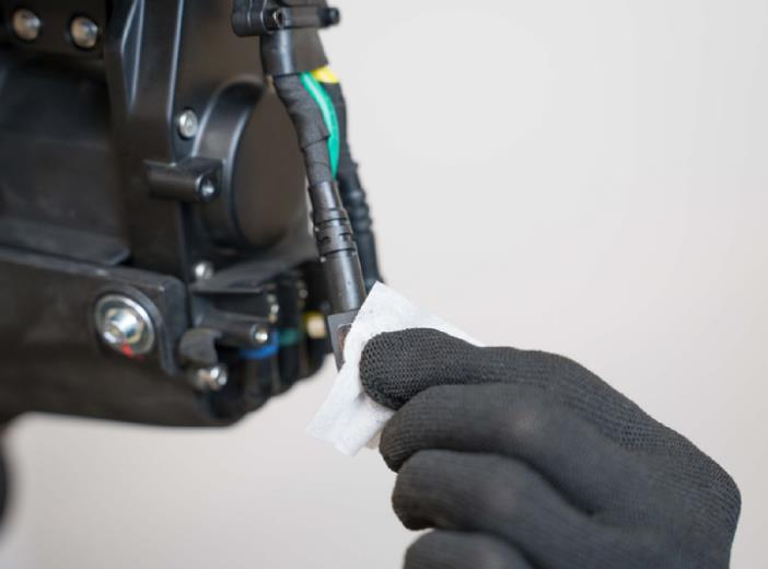
Inspect Battery Connector: Visual inspection to ensure battery connector is clean, dry, and free of defects. Use cotton swab to clean any debris on electrical contact. Ensure the battery connector plug allows small movement. If the plug is stuck, reassemble. |
 |
|
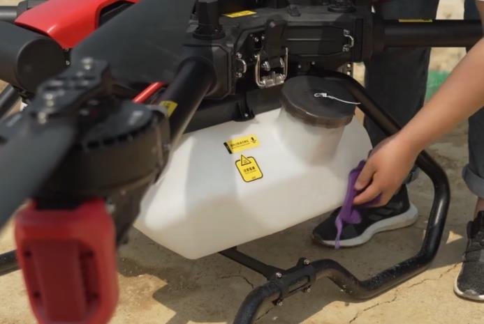
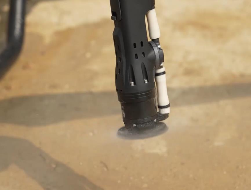
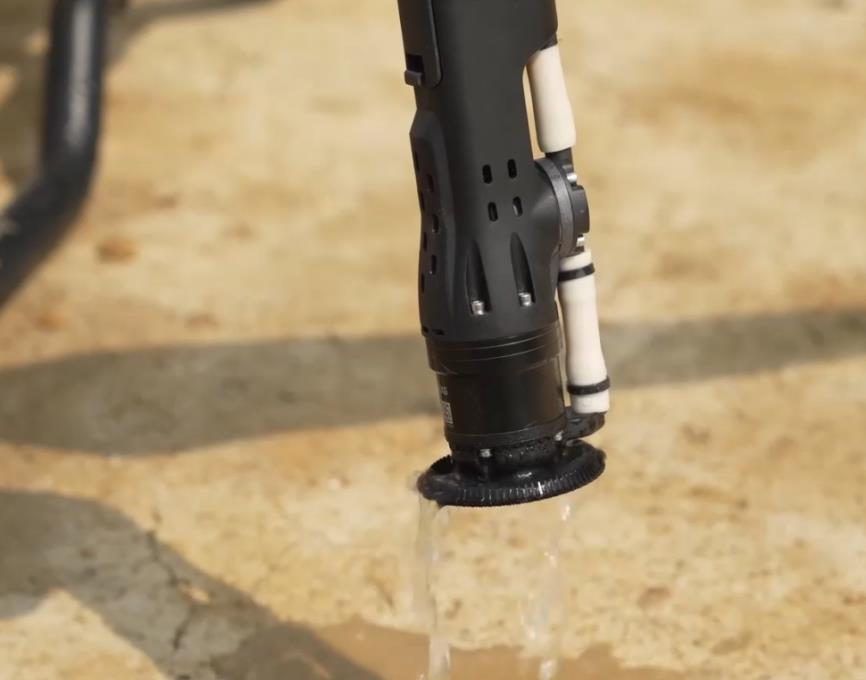
Sprinkler System Test: Start the spraying system and observe the atomization effect of the sprinkler. Check whether there is divergence and whether the sprinkler is blocked. If the sprinkler is blocked, remove, and clean it to prevent an uneven spraying effect and excess pressure from damaging the spraying system. Check whether the nozzle and exhaust valve leak water. If yes, replace the sealing gaskets at these two positions. |
 |
|
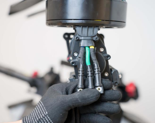
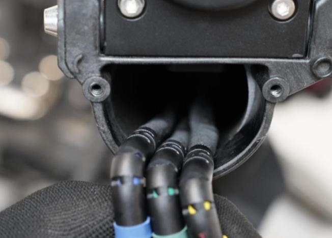
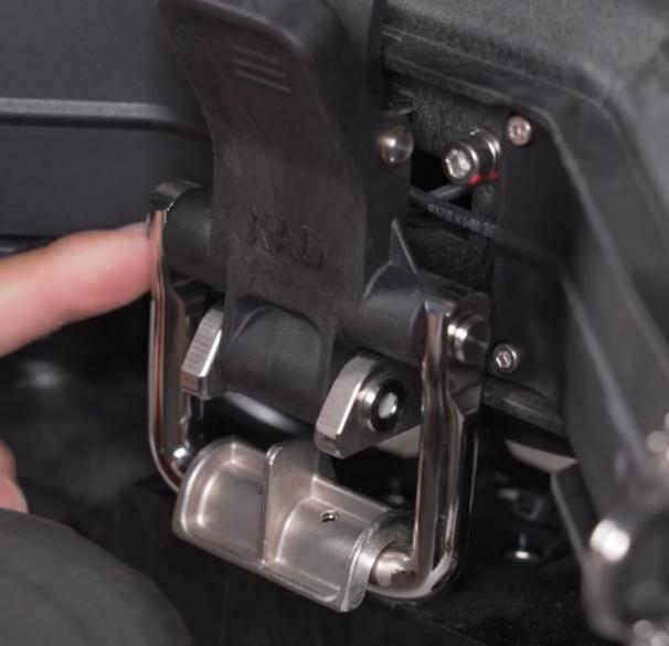
Hose Connectors: Manually check whether the hose connectors are loose, and visually check whether the connectors are damaged. (See figures below). If damaged, replace them immediately, or air will enter the hoses and cause malfunctioning. |
 |
|
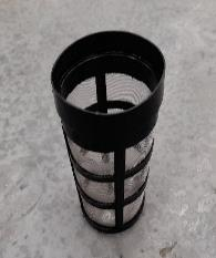
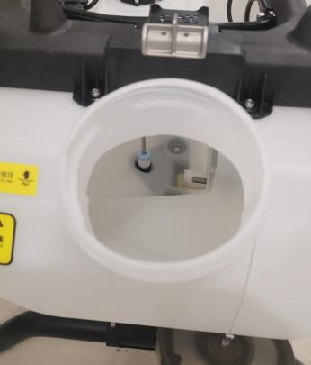
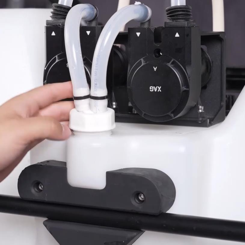
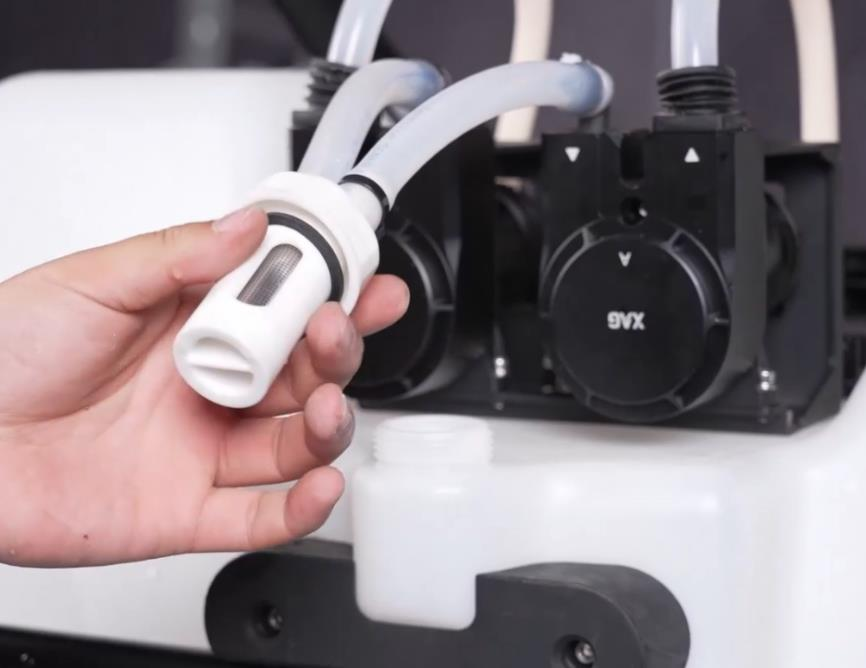
Check Hose Manually and visually inspect hose to check whether it is broken or worn. Check filter and liquid level gauge: Remove the liquid tank lid and take out the mesh filter basket. Ensure that the liquid level float gauge is not stuck and is free moving. Clean any debris on mesh filter basket. |
  |
|
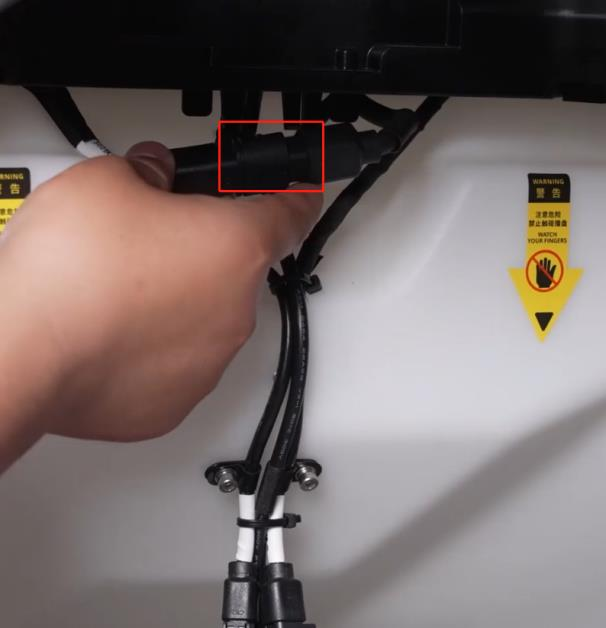
Check Charging System Connector: Inspect the charger and water tank plug (if using cooling tank) and ensure the plugs are clean and free of debris. Clean any debris and ensure all electrical plugs are dry before use. |
|
|
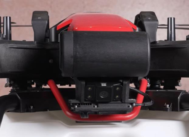
Inspect Radar: Visually check whether the main front radar mount is deformed. If there is deformation, it should be replaced immediately. The deformation of the radar mount will affect the radar detection ability. Radar Cable should be on the left, reinstall radar if incorrect. |
 |


Daily Clean After Flight Mission Completed
The following Daily Post-Flight Clean must be conducted if the aircraft has been used for the application of agrichemicals.
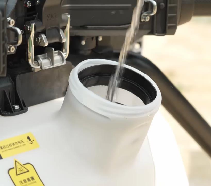
- Refill the Tank with soap water or soap powder and water. Engage all nozzles to drain and clean out remaining residues within the spray system.
- Refill the Tank with clean water and engage all nozzles to drain and clean out remaining soap water within the spray system.
- Place an empty Tank and engage all nozzles to drain and clean out any remaining residues within the spray system to avoid residues leaking during transportation.
- Use a water-filled spray washer to clean the aircraft body and wipe it with a soft brush or wet cloth before cleaning water stains with a dry cloth.
- Wring a wet rag, then wipe and clean the exterior of the aircraft to remove any stains and foreign objects. Wipe and clean the propellers. Wipe and clean the motor housing.
- Wring a clean wet rag, then wipe and clean the remote controller.
- Use a clean damp microfiber cloth to clean the terrain module; ground radar and ground vision lens to ensure that the terrain module is clean and free of foreign debris.
- Use a lens or microfiber cloth to wipe the perspective image camera and check whether it is functional through the XAG One App.

Instructions for Recording Inspections
Use the XAG Major Inspection Schedule of this manual. This inspection schedule includes all items in the XAG Guidelines plus additional items specified in the documentation for authorized Dealers and Service Agents.
- Record the model and UAV nameplate (FC-SN, UAV-SN) for the aircraft.
- Record the date, flights, and flight hours that the inspection was due, and the actuals for this inspection.
- Calculate and record the date, flights, and flight hours that the next inspection is due:
a.Date Next Due is earlier of Date Due and Date This Inspection, plus 6 months
(for the 6-Month Inspection – the only calendar-based item).
Flights Next Due is the lesser of Flights Due and Flights This Inspection, plus the inspection period specified in the Maintenance Inspection Cycle table.
c.Flight Hours Next Due is the lesser of Flight Hours Due and Flight Hours This Inspection, plus the inspection period specified in the Maintenance Inspection Cycle table.
- Work through the checklist and take the indicated remedial actions as required. Initial each row once the inspection and any associated maintenance is completed.
- Once completed the checklist should be signed, dated, and filed. A summary entry must be entered in the UAV Maintenance and Modifications Logbook, noting that the inspection has been completed and any rectification or maintenance conducted as a result of the inspection.
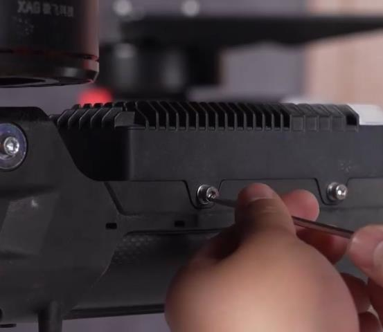
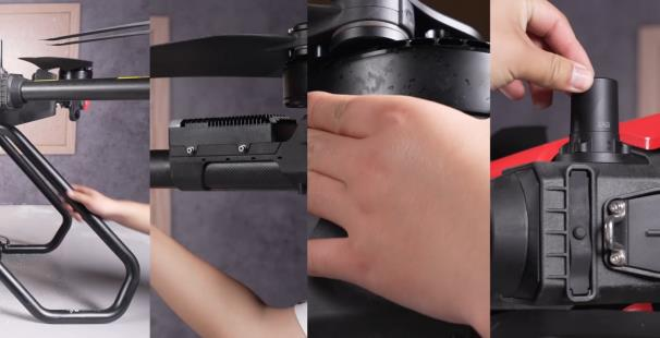
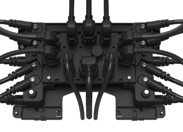
10 Hour Check
The 20 Hour Check consists of an inspection of high use parts and critical systems as detailed below.
 Make sure wear clean ESD safety gloves before check.

Critical Check for P100
| Procedure | Photo |
|
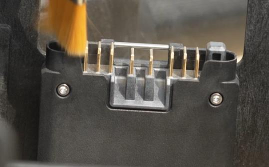
[Important] Use alcohol for deep cleaning. Remote all the impurities, sweat, dust from the metal plates. |
 |
|
Inspect if the rubber connectors are worn out (crackles, flaw, damaged, etc). |
 |
|
Inspect if the cables are intertwined or worn out (crackles, flaw, damaged, etc). |
 |
|
Inspect the cable connection of motors and ESCs from loosening. Torque: 25-26kgf.cm
|
 |
|
Inspect the ESC screws from loosening |
 |
|
Wire inspection: Remove the cover and check whether any wires are worn-out, broken or loosen. Replace if necessary. |
|
|
Inspect screws from loosening |
 |
|
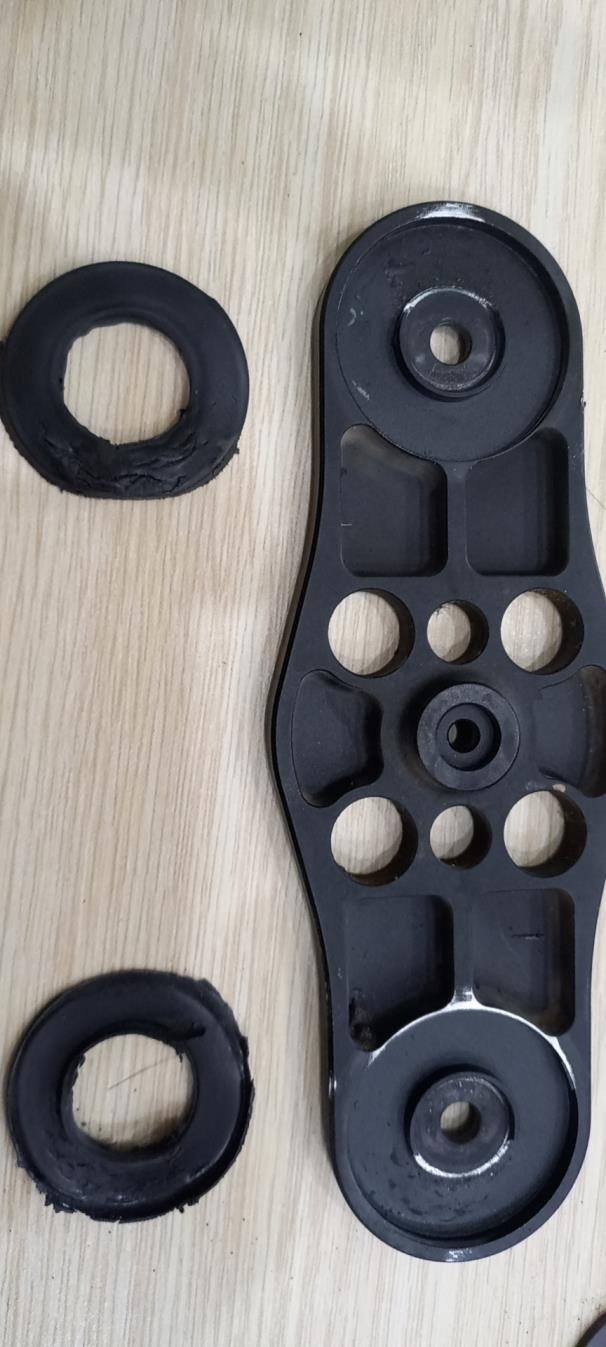
Inspect the rubber ring inside propeller clip. Replace rubber ring if it’s worn out.
|
 |
 It’s important to perform service maintenance once a period.
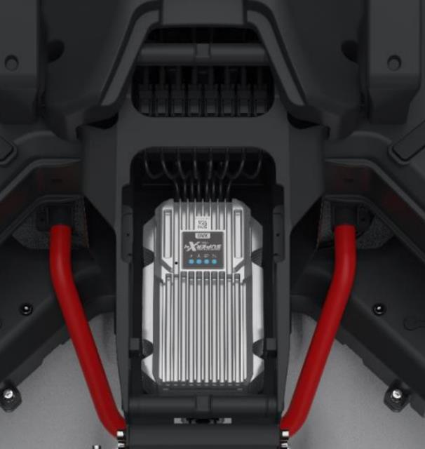
The below pictures show that wire burned due to screw loosen.
This is because during flight, UAV will be suffered from serious vibration, which inevitably result in loosen screws. From the below picture, it is the consequences of loosen motor connectors, where connectors burned, motor stopped, then UAV crashed.


Thus, it is important to have the practice of clean and fasten, or even replace the screws and relevant pars.
Routine Check
|
Procedure |
Photo |
|
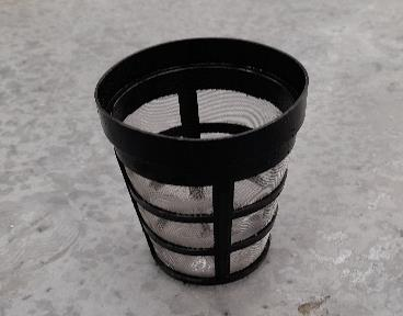
1.Strainer / Filter: Inspect and clean Replace if damaged. |
 |
| 2. Remote Controller: a) Clean Remote Controller and check whether it is corroded. b) Check whether Remote Controller can be powered on and function normally |
 |
| 3.Tail Plug Power Cord Inspection: Remove the drone battery plug housing, and visually check whether the power supply cables of the plug are damaged, whether the power cable connectors are fused or broken, and replace any abnormal tail plug in the power system |
 |
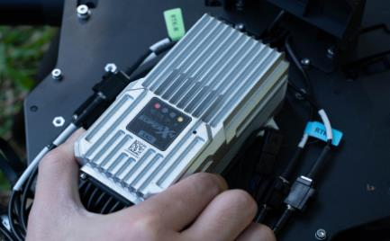
| 4.Firmware Updates: After powering on the drone, check the firmware version of each device and module through the XAG One app and upgrade to the latest version if possible. |
|
| 5.Flight Control Checks: Check whether the flight computer mounting bracket is firmly fixed. Ensure there are no error codes broadcasted through any of the status lights. |
 |
|
6. Releasable hood and lock Inspection: Inspect the releasable hood and lock from loosening, deforming, eroding |
 |
|
7. Inspect cable connector from loosening, eroding, deforming |
 |
| 8.Inspect the UAV from physical damage, deformation, cracks |  |
| 9. Inspect the joint of motors and base from loosening |  |
| 10. Inspect the joint tightness between propellers and clips | 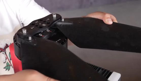 |
| 11. Inspect the screws (motor/clip) from missing or loosening | 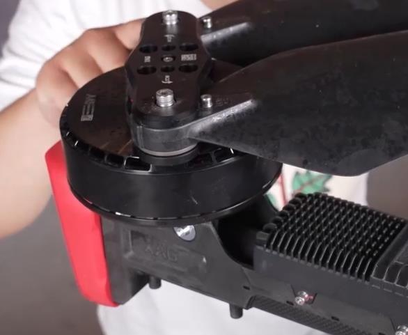 |
| 12. Inspect its bearings from loosening or abnormal sound. Rotate the motor to check the motor bearings | 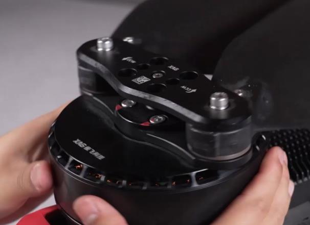 |
| 13. Inspect the ESC from containing chemicals or other impurities | 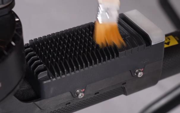 |
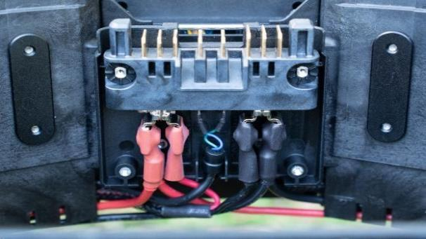
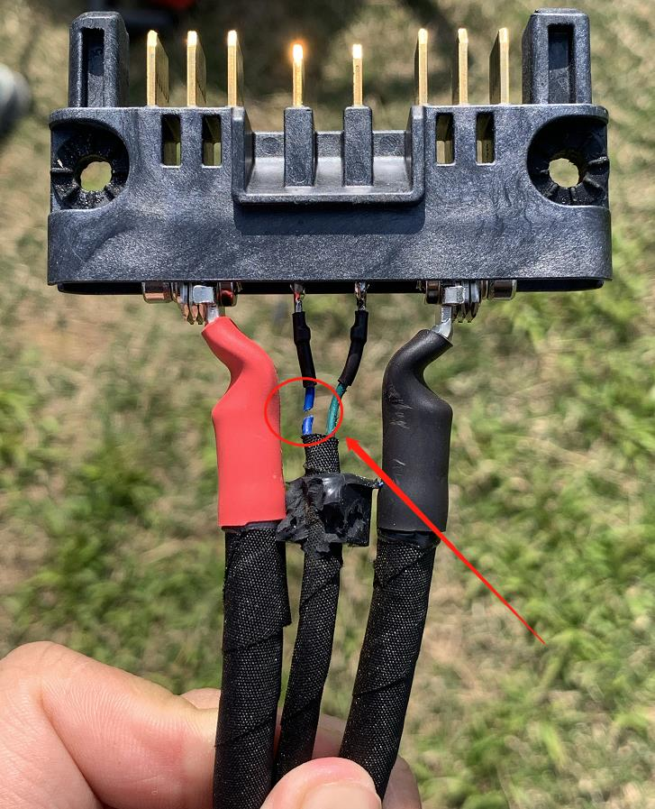
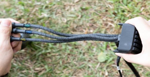
Battery charge plug should be inspected regularly, make sure that the cable is in good condition.
The below picture shows the cut off signal cable of battery plug.
20 Hour / 6 Month Inspection
The 100 Hour / 6 Month Inspection consists of an inspection of critical parts and systems as detailed below.
| Procedure | Photo |
|
Detailed Airframe Inspection: Check the aircraft structure, arms, main beams, and carbon frames to ensure there are no deformities, cracks, or breaks. Replace any unfit or broken parts. |
 |
|
Screw inspection: Use a screwdriver and Allen key to check whether any fixing screws of the fuselage are loose, slippery, rusted or broken, and replace any damaged screws. |
 |
|
ESC Wire Inspection: Check if the three-phase wires and terminals of the ESC are worn or broken. It is necessary to wrap the three-phase wires of the ESC with Acetate Cloth Electrical to ensure that the wire shielding is not exposed. Replace any ESC with damaged wires. |
 |
|
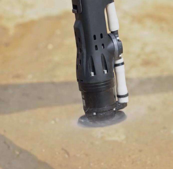
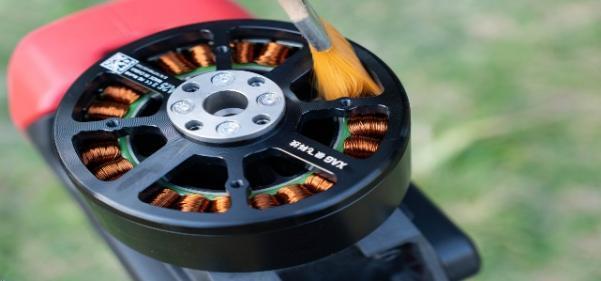
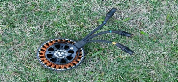
Motor Inspection: Remove the propeller and motor cover. Use a soft brush to clean any debris, foreign matter, or dust on the caged wire of the motor. Visually check whether the caged wire of the motor is discolored. Replace motors if necessary. |
 |
|
Motor Wire Inspection: Check whether the three-phase wires and terminals of the motor are worn or broken. It is necessary to wrap the three-phase wires of the motor with Acetate Cloth Electrical tape to ensure that the wire shielding is not exposed. Replace any motors with damaged wires or terminals. |
 |
|
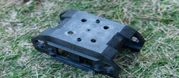
Motor mount inspection: Disassemble the motor and check whether there are obvious abnormalities such as cracks on the motor mount. |
 |
|
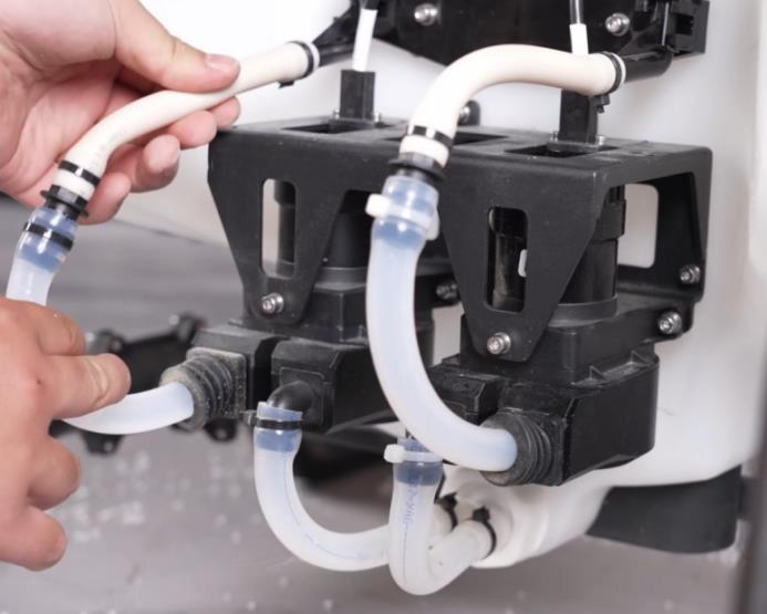
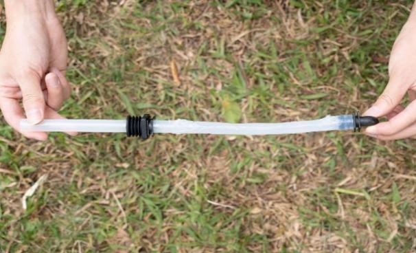
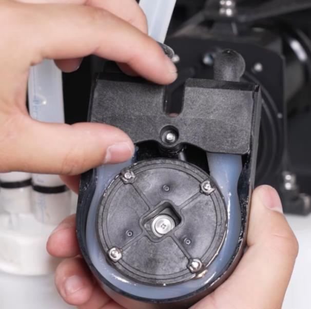
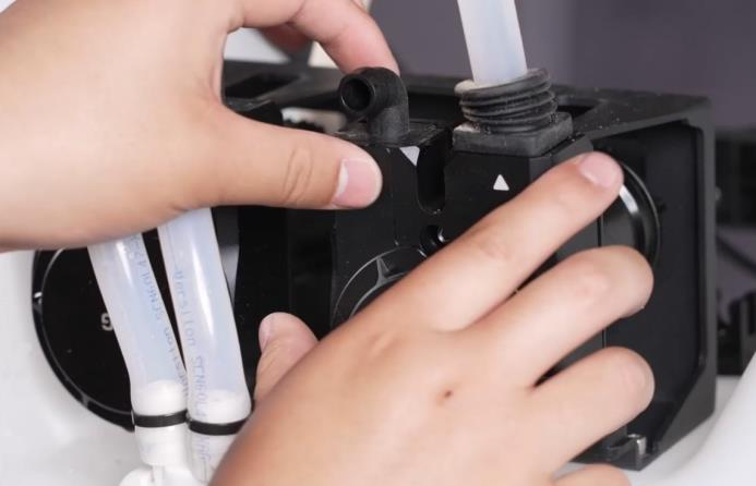
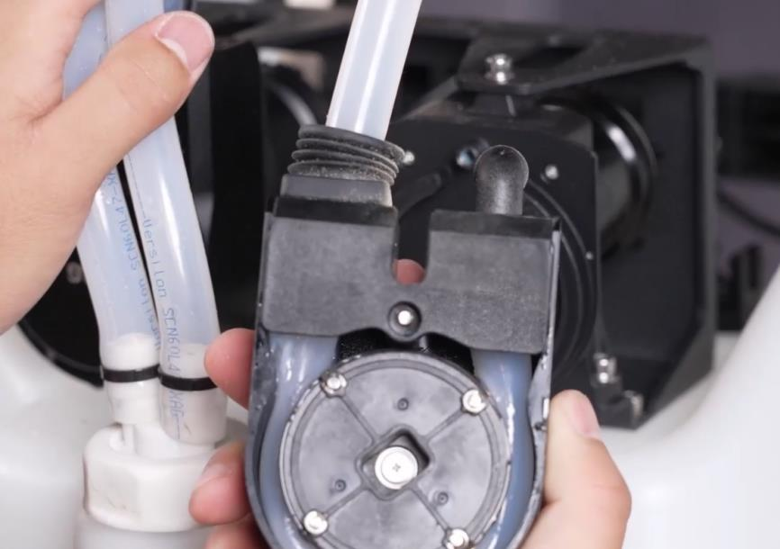
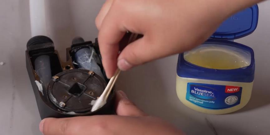
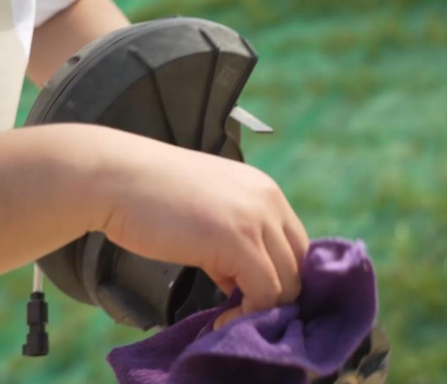
Peristaltic Pump Tubing Inspection: Remove the peristaltic pump. Check whether the peristaltic pump tube is blocked. Clean any debris or foreign matter in the peristaltic pump tube. Observe whether the peristaltic pump tube is showing age or damage and replace any aged or damaged peristaltic pump tube and conduct a spray calibration in the XAG One app. The peristaltic pump tube with no abnormality should be properly lubricated with the synchronizing plate. If the lubrication is poor, plain Vaseline or petroleum jelly should be applied. |
  |
|
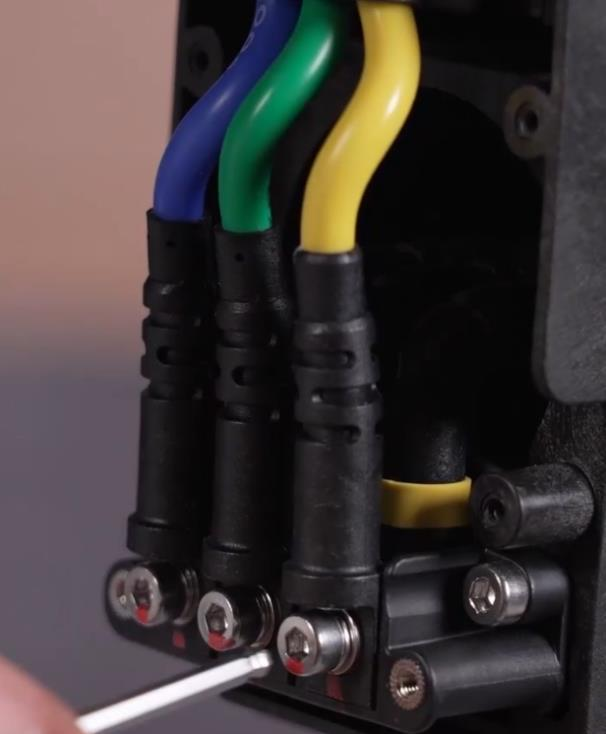
Electrical Connector Inspection: Check and ensure all electrical connectors are not loosen or disconnected with any fasteners in place. Tighten any loose connectors and replace any connectors which are damaged. |
Torque Tension Reference
|
P100 TORQUE-TENSION REFERENCE GUIDE |
|||
|
Main part |
Sub parts |
Torque tension reference |
Requirements |
| Front | Front and Main Fuselage Dynamic Radar Propeller ESC Arm and Main Fuselage |
29-31kgf.cm 21-22kgf.cm 48-52kgf.cm 12-14kgf.cm 29-31kgf.cm |
- - - - - |
| Motor Bracket and Motor | Preload: 35-41kgf.cm | Install in Diagonal sequence | |
| Tightening: 49kgf.cm | Red Mark | ||
| Arm | Arm and Motor Bracket | Preload: 35-35kgf.cm | The threaded end of the sleeve faces outward |
| Tightening: 49kgf.cm | Red Mark | ||
| Motor and ESC connector |
25-26kgf.cm
|
Follow cable colors | |
| Wipe the metal contact with alcohol | |||
| Main Fuselage |
|
Installation direction | |
| Central Power Busbar |
12-14kgf.cm |
No cable entangled; Arm 3 and Arm 4 cable should avoid interference |
|
|
|
Check whether the plastic is cracked |
||
| ESC input cable |
25-26kgf.cm |
- |
|
| Application System Mount | 12-14kgf.cm |
No cable entangled; Positive cable inward; Negative cable outward |
|
| Tail Frame |
Tail Frame and Main Fuselage |
29-31kgf.cm |
- |
|
Tail Socket Cable |
25-26kgf.cm |
- |
|
| Real Terra/ RevoSpray |
Liquid Container and Landing Skid |
13-14kgf.cm |
- |
|
Application System Upper |
21-22kgf.cm |
- |
|
| V40/V50 TORQUE-TENSION REFERENCE GUIDE | |||
|
Main part |
Mounting parts | Torque control point | Installation Requirements |
| Main Fuselage Frame | Dynamic Radar Cable Hub Clamp Sensor Bracket Quick Release semi-finished products |
11-12kgf.cm 11-12kgf.cm 11-12kgf.cm 11-12kgf.cm |
- - - - - |
| Tail Frame and Socket |
Preload:11-12kgf.cm |
Use alcohol to wipe the metal contact and the tail plug | |
|
Tightening:30kgf.cm |
|||
|
Arm and Main Fuselage |
80-90kgf.cm |
The bolts are locked and fixed by the flange locknuts, and the main arm steel shaft gasket should be placed under the nuts | |
| Arm |
Propeller |
48-52kgf.cm |
- |
| Motor Bracket and Servo |
Preload:25-27kgf.cm |
- | |
|
Tightening:60kgf.cm |
- | ||
| Motor Bracket and Motor |
Preload:25-27kgf.cm |
- | |
|
Tightening:60kgf.cm |
- | ||
| Motor and ESC connector |
24-26kgf.cm |
Color matching Wipe the fixed terminal surface with alcohol |
|
| The connect of Servo and Arm |
Preload:25-27kgf.cm |
- | |
|
Tightening:60kgf.cm |
- | ||
| Servo Arm Connecting Rod(Rocker Arm) |
Preload:25-27kgf.cm |
- | |
|
Tightening:60kgf.cm |
- | ||
|
Servo Arm Connecting Rod(Connecting Rod) |
Preload:25-27kgf.cm |
- | |
| Real Terra/ RevoSpray |
Liquid Container and Landing Skid |
13-14kgf.cm |
- |
|
Application System Upper Frame and 药箱 |
21-22kgf.cm |
- | |
Propulstion System
As the dust or chemicals can erode the physical parts of UAV, it will shorten the lifespan. Thus, please wash and clean the UAV every time when the operation is finished.
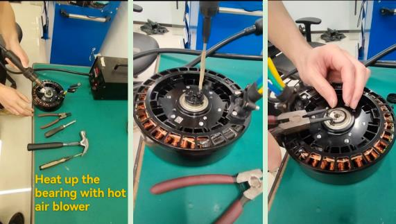
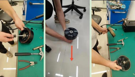
In case that there is foreign object or something that makes the motor stuck that cannot be removed from outside, here is the method to separate the motor:
RevoSpray System
As the chemicals can erode the physical parts of UAV, it will shorten the lifespan. Thus, please wash and clean the UAV every time when the operation is finished.
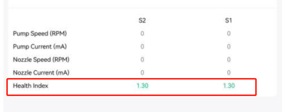
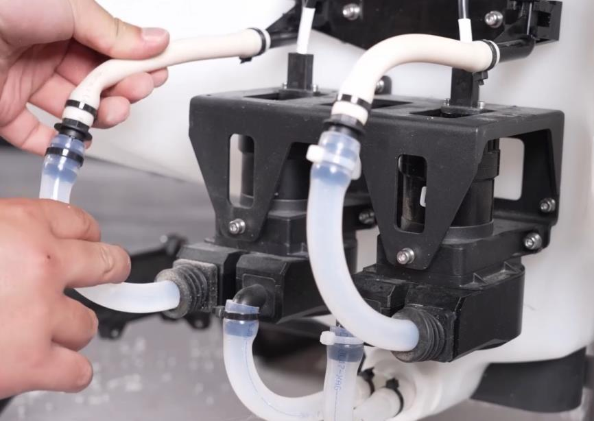
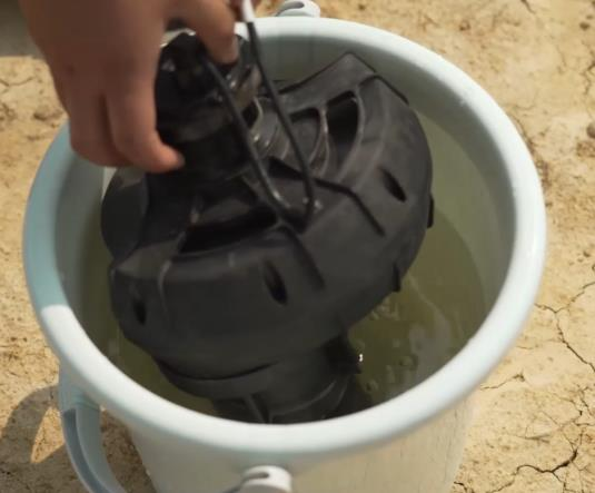
Before spray operation, it’s suggested to calibrate spray system using clean water. Make sure that the health index is OK and shown in green. If not, please inspect the peristaltic pump and rubber tube. Replace them if necessary.
Inspect peristaltic pump
Disassembly peristaltic pump
Inspect the lubrication between peristaltic pump internal rubber tube and plate synchronizer
Apply lubrication If necessary
Inspect the rubber tube circuit
Inspect the external rubber tubes circuit
Remove the filter underneath the liquid tank
Clean the filter from dust and impurity
Use soap and washing powder to clean the liquid tank internal

Pour soap water into liquid tank and use manual spray mode to clean spray system.
This can remove the chemical residue inside liquid tank.
Pour into clean water
Emit the water from liquid tank to clean spray system again.
This can clean and eliminate the soap residue inside liquid tank.
Make sure the liquid tank is empty after cleaning
RevoCast System
It’s important to deeply clean the RevoCast system after the operation, from entangling, Fertilizer agglomerating, losing accuracy, etc. These will significantly affect the operation of RevoCast system.
The below pictures shows that Revocast parts worn out due to the lack of cleaning.


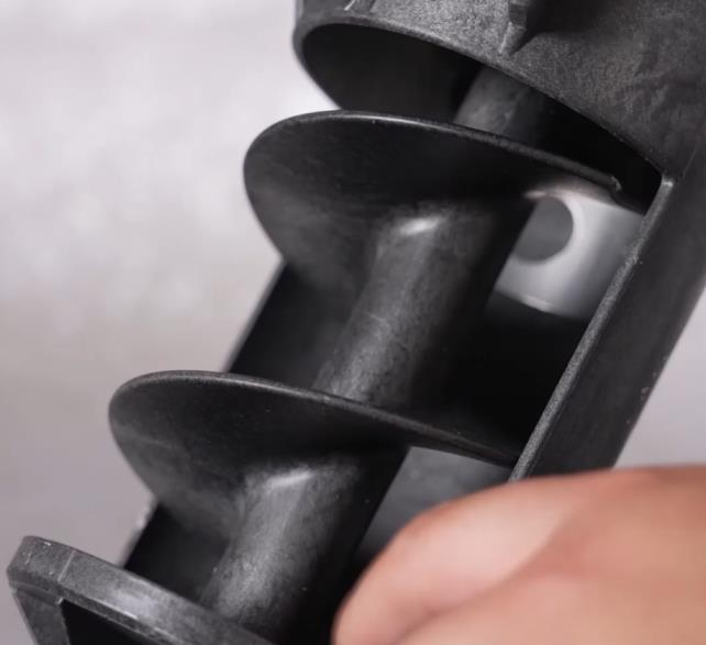
Clean Spiral Feeder
Soak spiral feeder into the clean water for 4~12 hours.
Use clean water to rinse spiral feeder. It’s recommended to use high pressure water gun.


Clean the spiral feeder from impurities with cloth
Impurities will jam the spiral feeder, resulting the inaccuracy of spreading.
Visual inspect Spiral Feeder
Perform regularly visual inspection of the spiral feeder worn-out condition.
If the worn-out thickness is more than 2 mm, please replace the spiral feeder immediately.
Make sure cross groove joint is clean


When placing the spiral feeder back to the slot, please make sure it follows the groove guide.


To lock the feeder easily, you are allowed to manually adjust the sprial feeder angle inside the container.


Reconnect the cable connectors


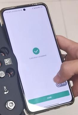
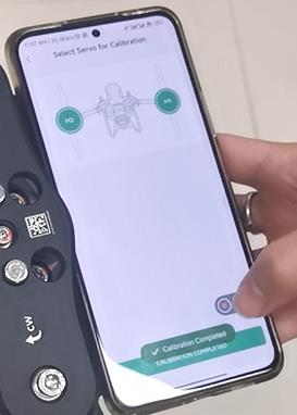
V40 Duo Propeller Drone
V40 Servo Calibration
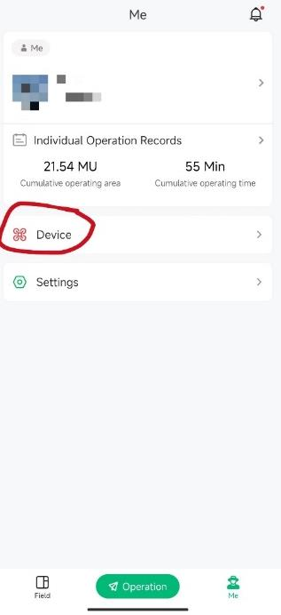
1. Open the XAG ONE app, click on me.
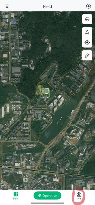
2. Click on device.
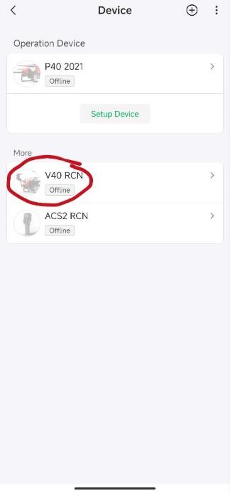
3. Click on your droneV40.
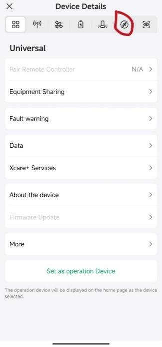
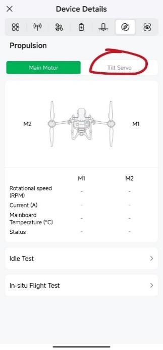
4. From Device Details, click on Propulsion.
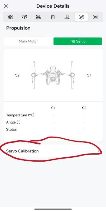
5. Click on Tilt Servo
6. Click on Servo Calibration
7.Expand the V40 arms according to the APP prompts.
Make sure the propeller is facing parallel to the V40, Click on NEXT.


9. Choose M1 or M2, place the smartphone on the top surface of the motor. Be aware of that the phone camera should not tilt up your smartphone. Then start auto calibration.


10. Finish Calibration. You can watch the below video to complete the calibration. Video link: https://drive.google.com/file/d/1EMlfm4XbIN7gucxXCrBTNVVdiLyiSQON/view?usp=sharing