.png?height=120&name=Pegasus%20Robotics%20Logo%20-%20Portait%20(2).png)
Mission Preparation
Limitation and Safety
Operational Limitations
- Maximum operating height of 30 meters AGL
- Maximum distance between aircraft and remote pilot or observer of 1000 meters
- Operations are limited to VLOS and EVLOS
- The remote pilot must operate one aircraft at a time, unless otherwise approved by local authorities
- The remote pilot must be able to take control of the flight during any flight phase
- Ensure a minimum Safety Margin of 30m between flight limit area and third party, ground structures or populated areas
- Ensure a minimum Safety Margin of 30m between flight limit area and authorized airspace limits
- Comply with MAPA (Crop spraying Activity) and DECEA (Airspace Access) regulations if applicable
Environment limitations
| Operating Temperature Envelope | 10~40 °C |
| Wind Speed Limit | 10m/s |
| Atmospheric condition | No significant meteorological formations |
| Precipitation | No rain |
| Visibility | Visual Meteorological Condition |
Local Evaluation: Ground Risk Assessment
- Identify the obstacles in the field, add the obstacles into the field map using ACS2 Rover
- Identify the terrain of the field, be aware of undulating land
- Identify human activities nearby
- Identify ground wind speed, humidity, and temperature
Flight Authorization Request
According to the local regulations and laws, please request flight authorization if necessary.
Personal Protective Equipment preparation
Safety is paramount in preparing pesticides, so please strictly follow the guidelines below.
- Check if your long sleeves, trousers, mask, goggles, and rubber gloves are worn out. Replace them when they do.
- Wear a mask, goggles, long sleeves, trousers, and rubber gloves before preparing pesticides upwind in an airy and shady area.
- NEVER smoke, eat or drink when spraying pesticides. When tubes or nozzles are clogged up, unclog them with soft objects or clean water. Do NOT blow them with your mouth.
- If pesticides get into your eyes, rinse them immediately with plenty of clean water. When you have symptoms such as headaches, nausea, and vomiting, stop the operation, take off your protective clothing and go to the nearest hospital with the packaging of the pesticides applied.
- Upon completion of the operation, wash your hands with soap and remember to wash your body thoroughly in time.
- Soak your protective equipment in lye and wash it.
- Pesticide containers and packaging must be collected for proper disposal. NEVER discard pesticide packaging in ditches, wells or places with people and animals, otherwise, pesticide hazards, poisoning or environmental pollution could occur.
Chemical Preparation and Care
Use pesticides in accordance with manufacturers' safety instructions.
- During operation, the protection of aircraft besides people is also important. Beware of liquid getting into the circuit board in the installation or removal of the liquid tank, causing short circuits and damaging the aircraft. Minimize malfunctions resulting from improper operation.
- Prepare pesticides with clean water as dirty or muddy water could reduce the dispersity, wettability, and permeability of pesticides in water, causing them to precipitate and become less effective. Impurities in water could break down part of the active ingredients in pesticides, reducing their effectiveness.
- After adding clean water, stir the solution thoroughly so that pesticides fully dissolve with fewer precipitates and thus become more effective. Do NOT use warm water in pesticide preparation as the solution could crystallize and precipitate as the water cools down.
Inspect Devices Battery
Before the mission, fully charge the batteries of smartphone, RTK station, ACS2 remote controller, LNT, and UAV. Replace the battery if it’s bulge.


Bring the power band to the field in case of smartphone and ACS2 remote controller short of battery.
Defining UAV Take-off and Landing points
The landing point is the same as take-off point. For safety concerns, please select the take-off point according to the below conditions:
- > 10 meters away from any objects and people.
- Out of restricted airspace. Routes of airlines, sensitive areas and danger zone
- Must be in flat and open field, without significant sand and rocks
- stay away from ditches, trees, buildings, power line, etc
Routine Check for LNT Network
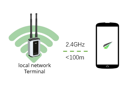
Check if Smartphone is connected to LNT network
LNT is directly connecting to smartphone through WIFI. The communication range between LNT and smartphone is less than 100 meters.
Check if WLAN mode is enabled
“WLAN mode” MUST be enabled during operation. This will significantly strengthen the WIFI signal and eliminate signal interference.
When the UAV is not under operation, you can use WAN mode for LNT network, firmware update, data sync, remote debug, etc.
Disconnect smartphone from 4G network
Some smartphones will simultaneously enable both WIFI and 4G if one or another are weak. This will seriously disturb the LNT communication channel. as the XAG One App is requesting data from the cloud server but not the LNT. The users may find the drone consistently switching between online and offline. To eliminate this risk, please disable the smartphone mobile data (4G), or turn on the smartphone’s flight mode. This action will only allow the smartphone to have access a unique channel, LNT hotspot.
Login XAG One account when LNT is offline
Disconnect LNT from internet, connect smartphone to LNT hotspot, login the XAG One account. Sometimes users may find that the XAG One account fails to login. This is due to the data lost from factory reset. To solve this, please reconnect your LNT to internet, login your account and wait an hour for data sync.
Firmware Update Using LNT
Make sure your LNT is connected to internet through WIFI router or hotspot, go to XAG One App, update all the devices’ firmware.
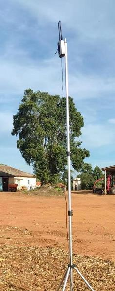
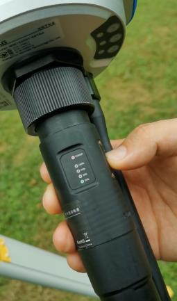
Positioning LNT
- Connect LNT to its battery
- Turn on LNT
- Check LNT LED indicators
- Disconnect LNT from internet
- Place LNT in a high and open space

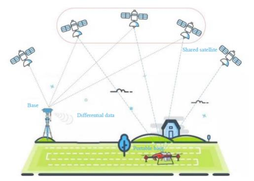
XRTK4 Portable Station Setup
Understand GNSS/RTK and XRTK4
XRTK4 Portable station is a GNSS/RTK base station that send RTCM corrections (stands for Radio Technical Commission for Maritime Services) to the Rover devices. The rover device are the mobile units, including ACS2 remote controller and UAV.
Signals from the Global Navigation Satellite System (GNSS) are one of the main inputs used for aircraft positioning or time reference for communication. It allows radio receivers to determine their 3D space position and time, with an accuracy of 2 to 20 meters. GNSS is a general term describing any satellite constellation, including several satellite systems, specifically used in different regions. nowadays we are talking about GNSS, not only about GPS.
Satellite systems are:
GPS - US
Galileo - Europe
GLONASS - Russia
BDS - CHINA
QZSS – Japan
GNSS/RTK accuracy depends on multiple factors, such as surrounding buildings, trees, vehicles, current weather conditions, numbers of the available satellites and more. The signals can be harder to get into the receiver if they are conflicted with surrounding distractions.
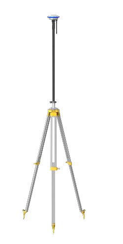
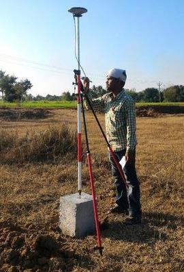
Positioning RTK Portable Station
Make sure that the ground is flat, and there are no surrounding distractions, such as budlings, trees, bad weather conditions, etc.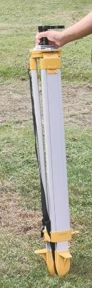
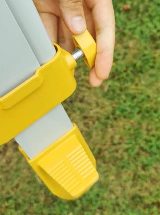
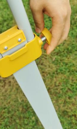
Adjust the screws to extend the legs of tripod
Place the tripod on the ground
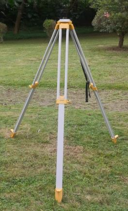
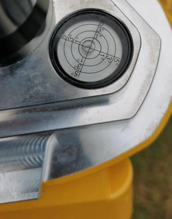
Adjust the bubble level within the accuracy of 1 degree
Put your foot onto the step, and fix the tripod on the ground

Turn on XRTK4
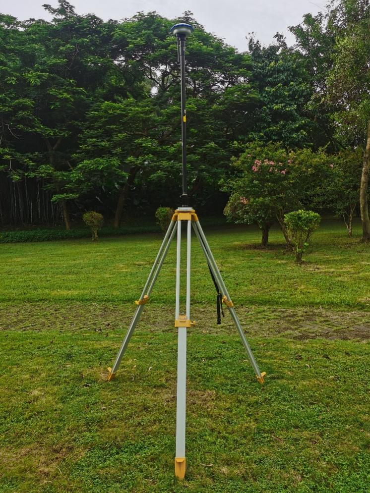
Insert XRTK4 into the tripod fixture slot, lock the clamp


The XRTK4 portable station set up is done
Single Point
Description:
This method allows a XRTK4 base station receiver setup at a known location, from where the rovers (UAV, ACS2) can get the GNSS positioning corrections. Even though this method is easy to set up and use, it has poor position accuracy compared to XRTK4 fixed station network, which usually contains more than one XRTK4 fixed station and they are communicating through 4G network. Thus, once you use the single point coordinates to map the field and want to use it again next time, you must save this coordinate
Question: When shall we manually select single point?
Answer: In LNT networking mode, users need to manually select single points.
But if in 4G mode where XRTK4 has 4G SIM card inserted, XRTk4 will automatically go into FIX.
|
Devices |
Network |
4G SIM required? |
FIX mode |
|
Portable XRTK4 |
LNT |
No |
Manual select single point, then go into FIX mode |
|
Portable XRTK4 |
4G |
Yes |
XRTK4 will automatically go into FIX mode |
|
Fixed XRTk4 |
4G |
Yes |
If there is nearby FIX station, XRTK4 will automatically go into FIX mode |
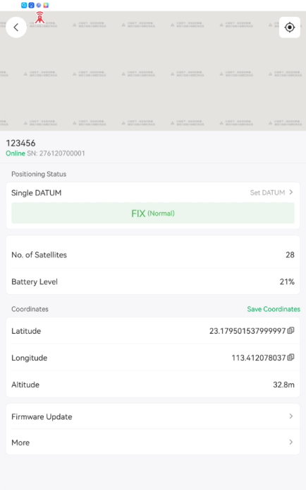
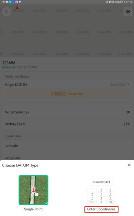
Procedure:
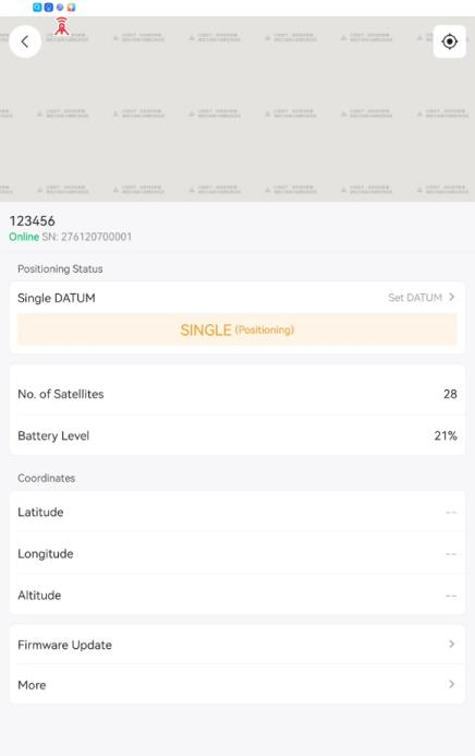
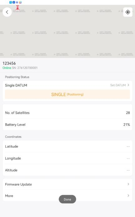
Choose the XRTK4 that need to set up
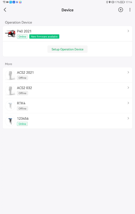
Press “Set Datum”
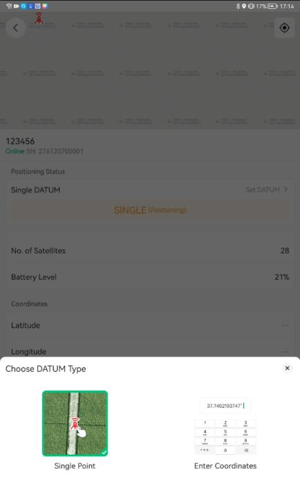
Choose DATUM type as single point
Wait for a while, this process may take up to 15 minutes
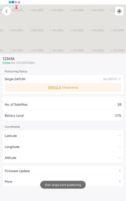
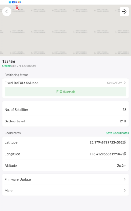
Once “FIX” is shown, the single point positioning is finalized Press “Save Coordinate”
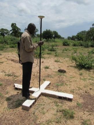
Input name and upload picture
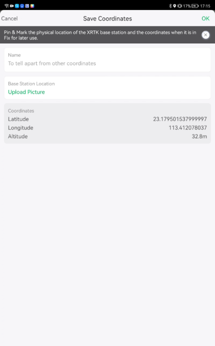
Take a picture of your XRTK4 portable station


Press “OK”
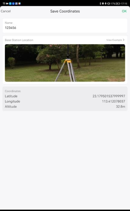
The coordinate is saved
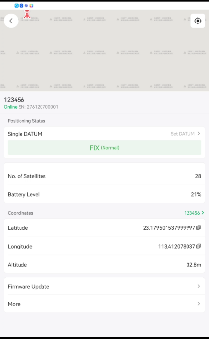
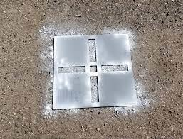
Before taking away your XRTK4 portable station, please mark on the ground.
So, when you come back to the field next time, you can place the XRTK4 portable station onto the exact spot where you marked.


Enter Coordinates
Before entering coordinate, you place the XRTK4 onto the exact spot that you put last time.
And then enter coordinates that save previously. This is because the fields that we mapped previously are based on the RTCM correction data, which comes from the XRTK4 portable base station at the exact spot that you put last time. Otherwise, UAVs will fly out of the field and possibly cause accidents.
Choose XRTK4 that need to setup

Press “Set DATUM”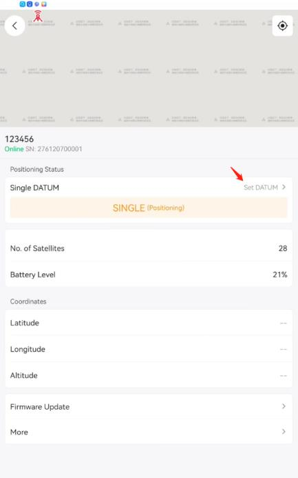
Choose “Enter Coordinates”
Choose “Use saved coordinates”


It takes approximately half a minute for XRTK4 positioning
Once the status of XRTK4 goes into “FIX (Normal)”, the XRTK4 setup is completed and it’s ready to use.
VRTK Flight and Offset Correction
VRTK flight introduction
Since 2023, users of XAG agriculture drones can fly without the RTK station, but only with GPS or VRTK. With VRTK, the flight mission can maintain a relatively high accuracy level for a certain period of time.
VRTK reference point is a base reference point set by the drone itself instead of using RTK station as base
reference. As the UAV moves, the UAV will keep remembering the initial physical position as base reference, also known as virtual reference point. The UAV positioning system automatically enters RTK by processing convergence to this virtual reference point, and the drone can maintain a relatively high accuracy level for a certain period, usually 2 hours.
Set VRTK Reference Point
1. Place the UAV on a safe and open spot, power it on and keep it still.
2. Select the UAV, go to Device details page, tap Positioning mode and select “VRTK Positioning”


3. Wait until the RTK Status changes to Active.


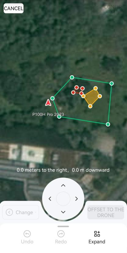
Offset Correction
Place the drone to the corner of field where you have marked a point during mapping.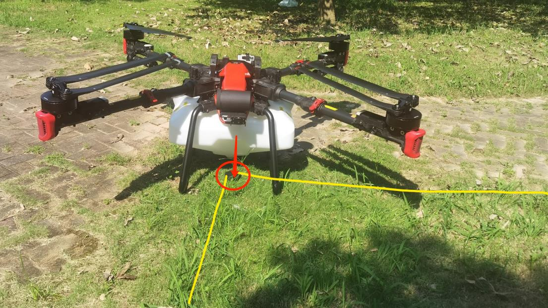
- Go to the operation page and select the field you are going to work on, you will find the UAV symbol is not exactly at the corner. There is a deviation from the point where it should be and you are required to perform offset correction. Tap “Offset correction” button on the screen


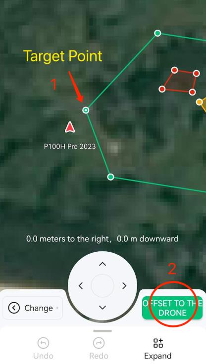
- The offset correction tool will then show up with all the points of the field displayed. You can either use the arrows to fine tune the position of the field map (each click moves 0.5 meters), or just select the target point of the map.
- Select the target point (field boundary reference point), and then tap “Offset to the drone” button
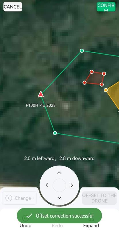
- Then the field boundary will move according to target point, which will match to the drone position (drone symbol), Tap confirm button on the screen to complete offset correction. Now the relative position of the drone and the field is correct
- It is safe to move the drone to a safe place to take off and operate. Perform the VRTK correction every 2 hours.
Precautions for VRTK flight
Before enabling VRTK mode, make sure the field is free of difficult terrain or obviousobstructions around that would affect positioning accuracy.
You should perform offset correction for the fields before performing a VRTK mode flight.
Anytime you conduct a cold restart, please perform field offset correction again for the drone to resume its operation in the same field.
When flying or mapping in VRTK mode, please complete the task within two hours, or please perform offset correction for each mission.
In VRTK mode, lower positioning accuracy may result from a combination of operating environment, fields satellite status, offset correction., which may cause missed/repeated sprays, collision, or crash and not be considered as device or VRTK malfunctions. Please be cautious.
Tips for VRTK flight
Instead of using the corner point of the field for correction, you may mark a redundant “no-spray zone” on the ground suitable for the drone to take off during mapping. Do remember to make a physical mark on the ground where you add points to the map, so that you can center the drone on it for field map correction.


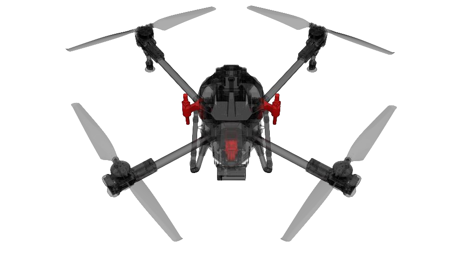
Pre-flight Check for UAV
Visual Inspection
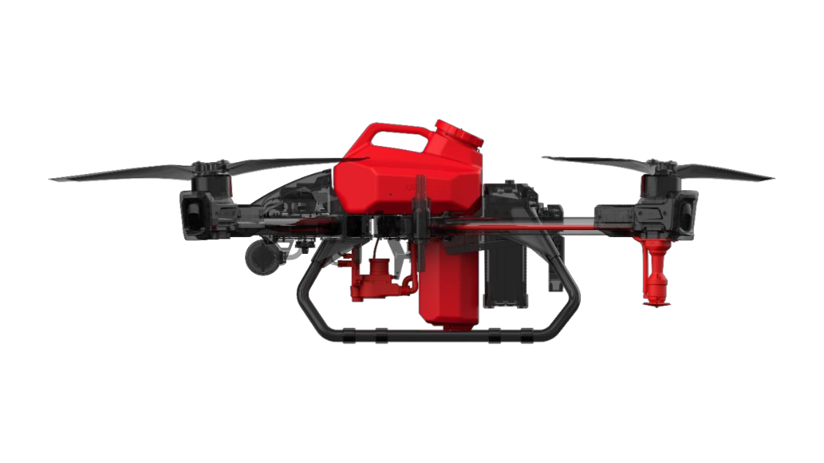
Please perform daily check before operation. Use P100 as example.
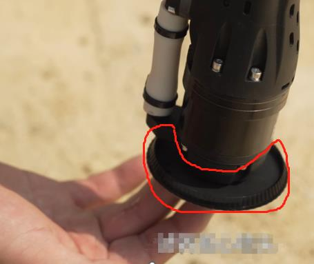
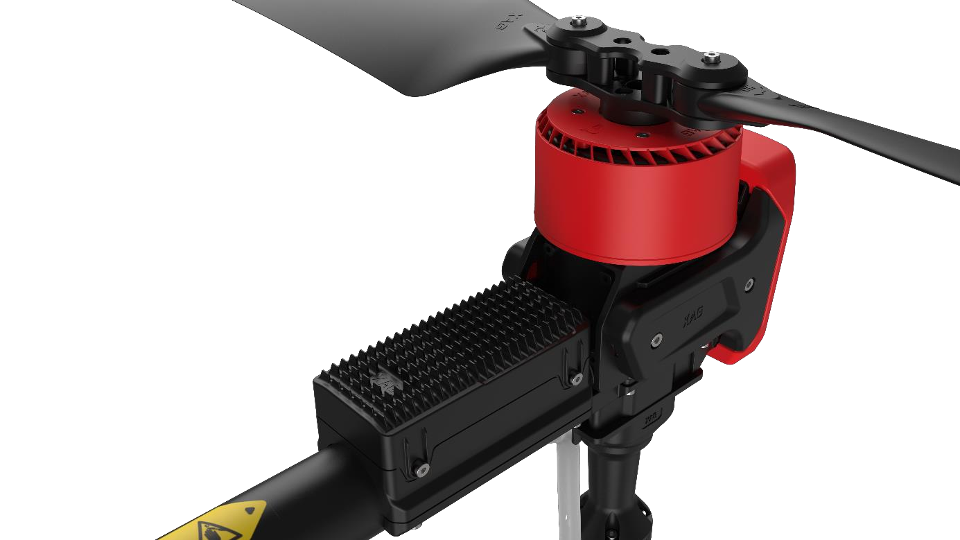
Propellers visual inspection
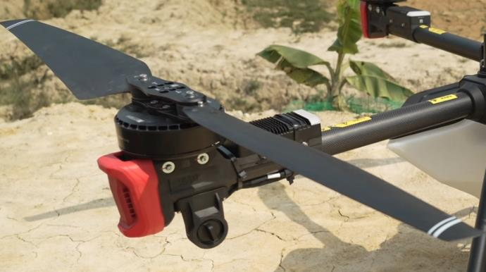
Arm visual inspection
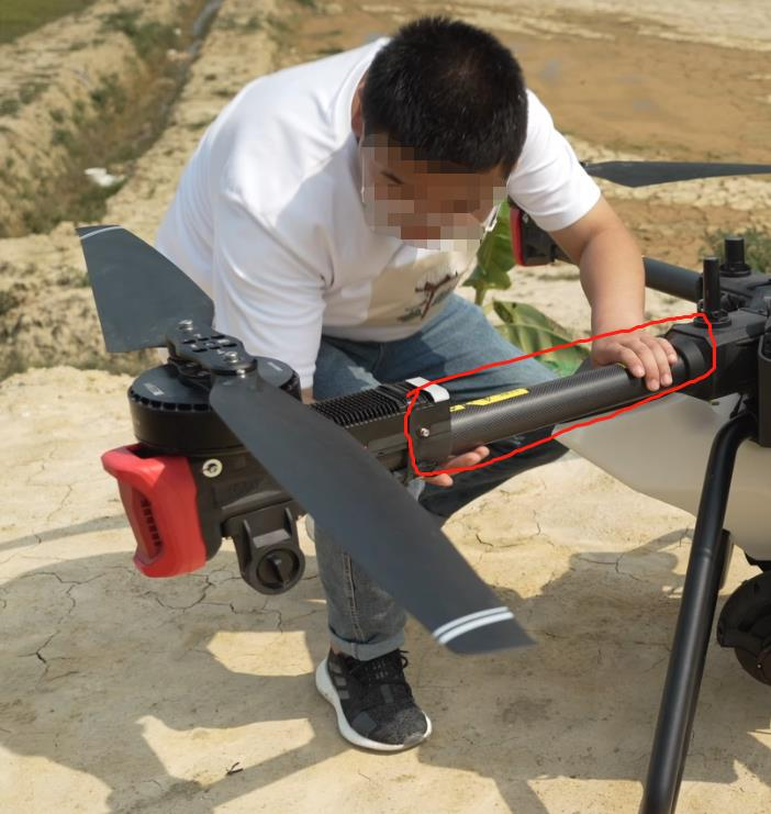
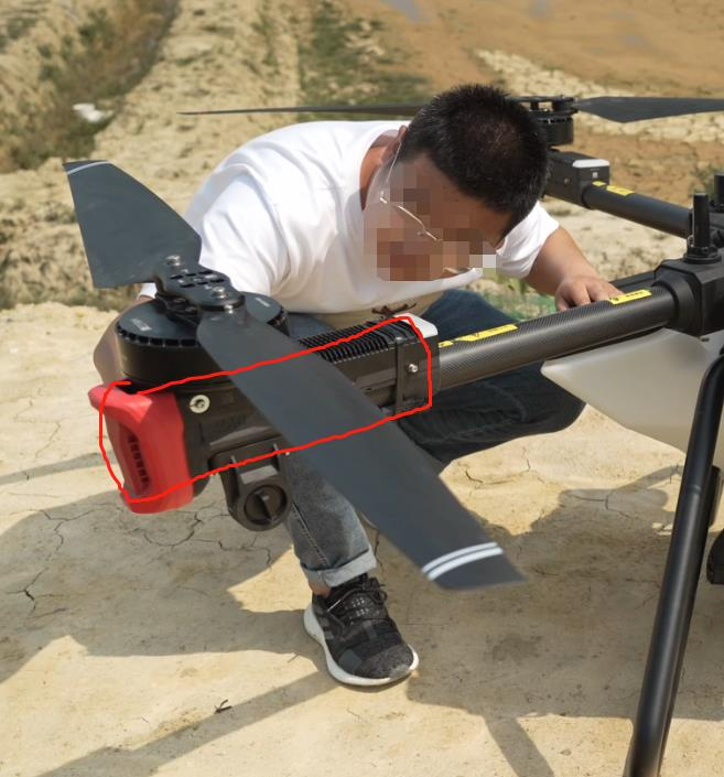
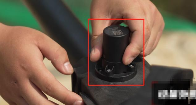
Motor base visual inspection
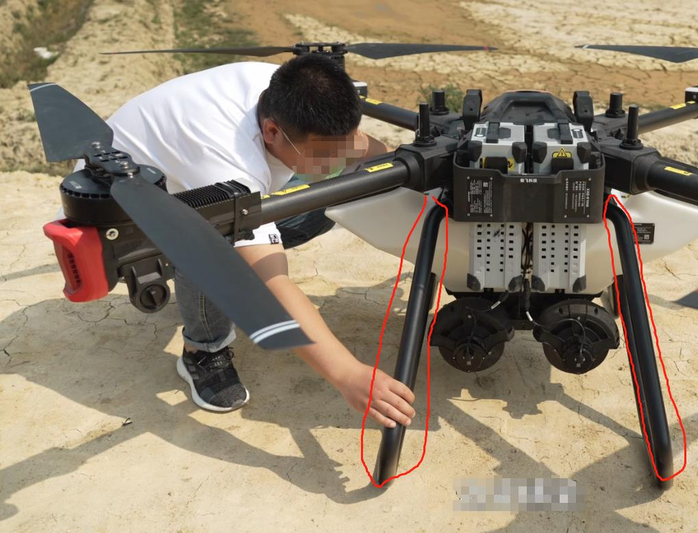
Rack visual inspection
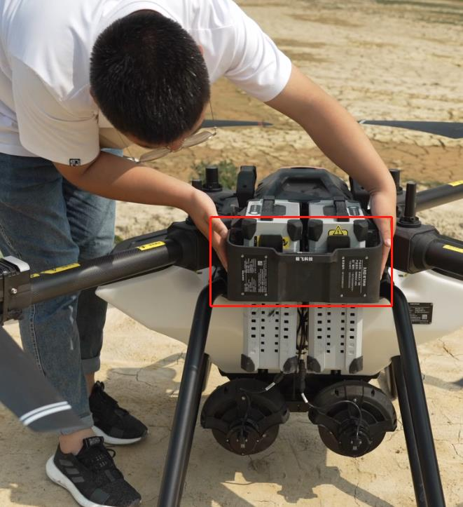
Battery rack visual inspection
Rotate motor to check if the motor is firmly installed into its base. Also listen to the motor to check if there is any abnormal sound.
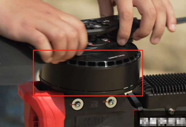
Rotate spray disk to check if the disk is firmly installed into the spray motor.
Check if the spray disk can be rotated smoothly.
Check if the spray disk is damaged.
Listen to the motor to check if there is any abnormal sound.
Check the RTK antenna installation
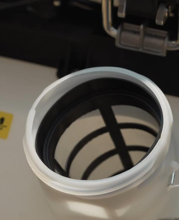
Inspect the liquid tank inlet
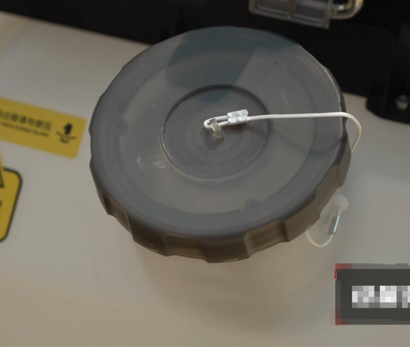
Inspect the filter. Make sure it’s clean and not damage.
Inspect the terrain module and optic flow
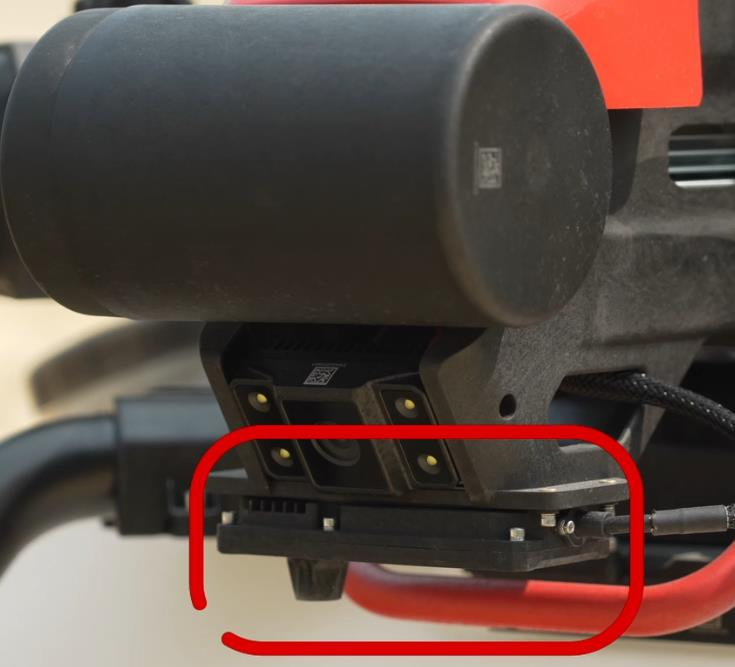
Inspect the PSL camera
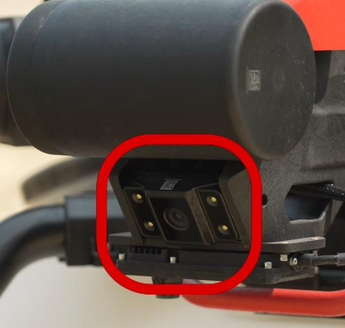
You may use lens cleaning cloth to wipe from the left to right


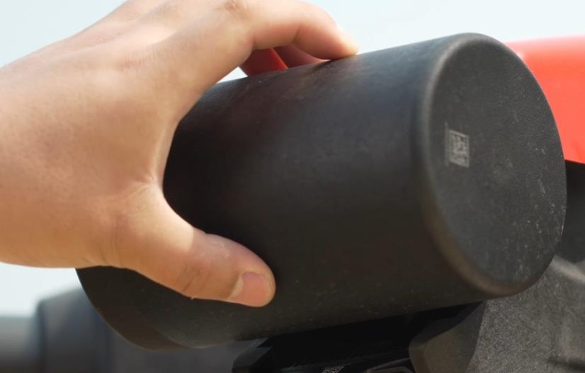
Inspect the dynamic radar
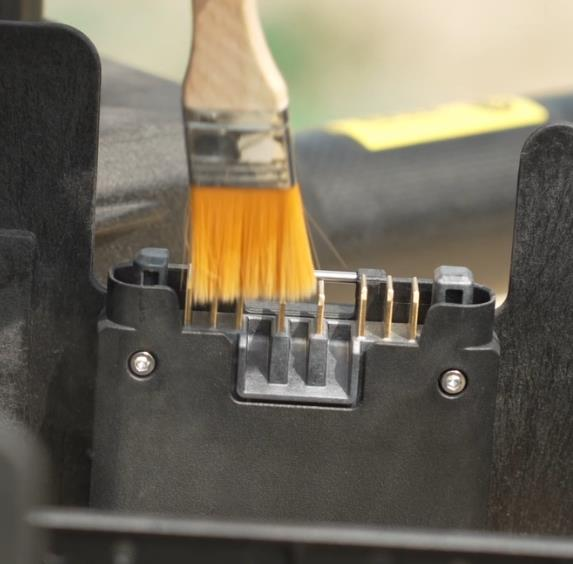
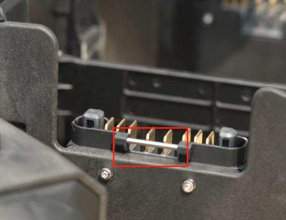
Clean up the battery socket
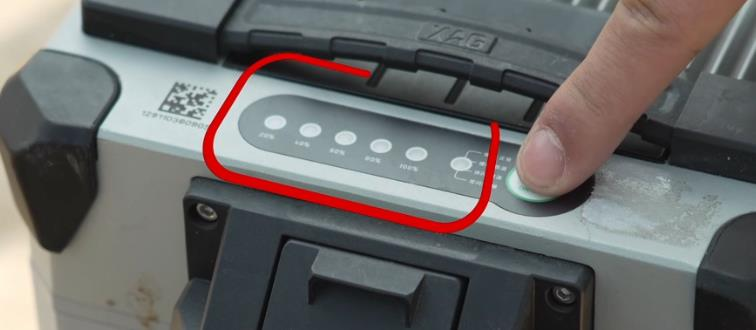
Check the remaining battery. Short press the smart battery power button
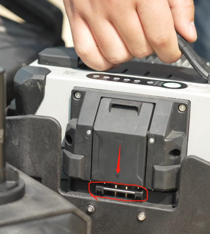
Inspect if the battery lock is damaged
Make sure you hear the clip sound when plugging the battery socket
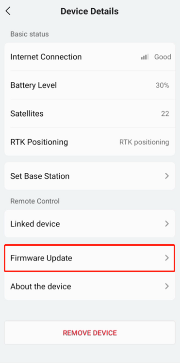
Firmware Update Check
Make sure your all your device firmware is updated to the latest version. If not, please update.
App Version Check
Make sure your App is updated to the latest version. If not, please update.

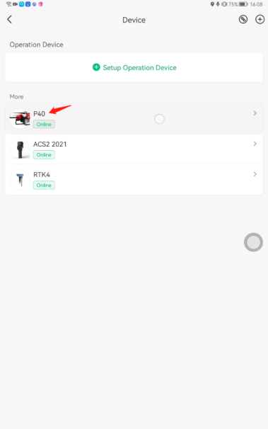
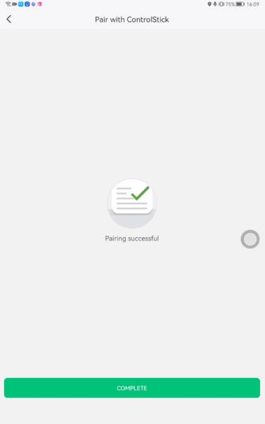
ACS2 Remote Controller Pairing Check
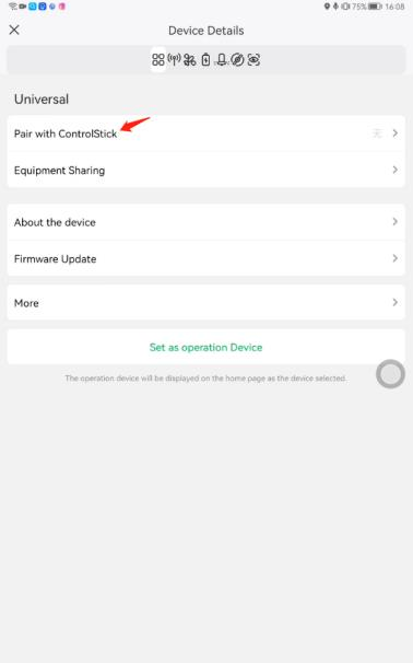
Go to UAV’s setting
Select "Pair with Control stick"
Select the ACS2 2021, and press "PAIR"
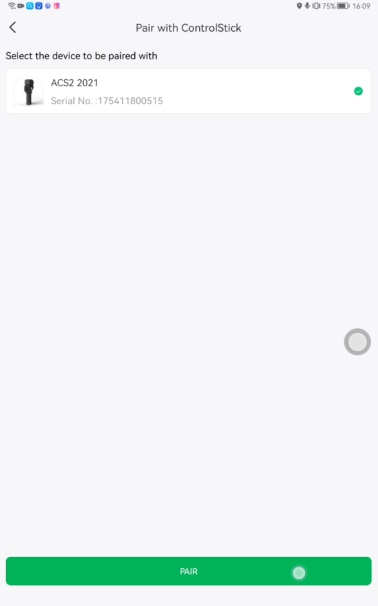
Pairing successful, press "COMPLETE"
UAV communication Check
If using 4G network, please check the IOT communication latency and packet loss.
If latency is greater than 300ms and packet loss is greater than 25%, the flight mission will be suffered.
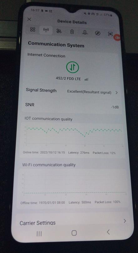
If using duo channel (WIFI/ 4G), please check both IOT and WIFI communication quality.
The UAV will decide to use the channel that has the lowest latency and packet loss.
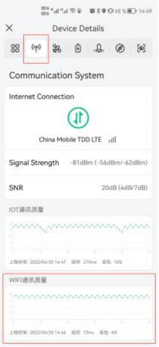
If you are using LNT, there are only WIFI signal active.
In summary
|
Communication signal |
4G network |
Duo channel |
LNT |
|
IOT (4G) |
Yes |
Yes |
No |
|
WIFI |
No |
Yes |
Yes |
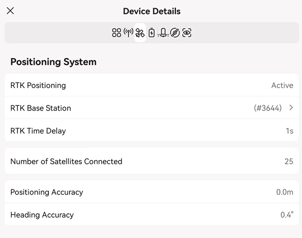
Positioning System Check
- Check if RTK positioning is “Active”
- Check RTK time delay less than 10s
- Check the number of satellites is greater than 16
- Check the positioning and heading accuracy (within 1.2)
Battery System


Check the remaining battery power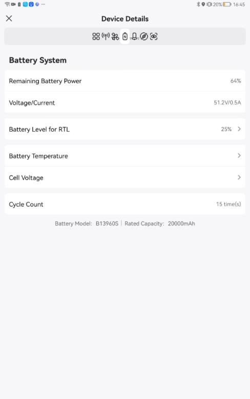
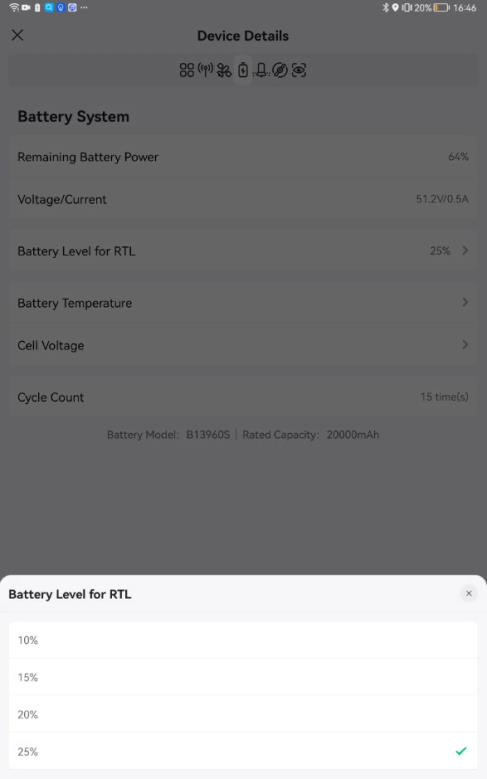
Battery level for RTL
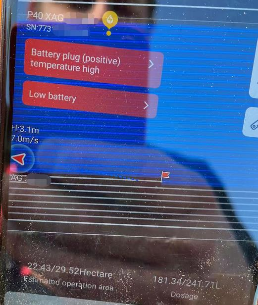
Check the battery temperature
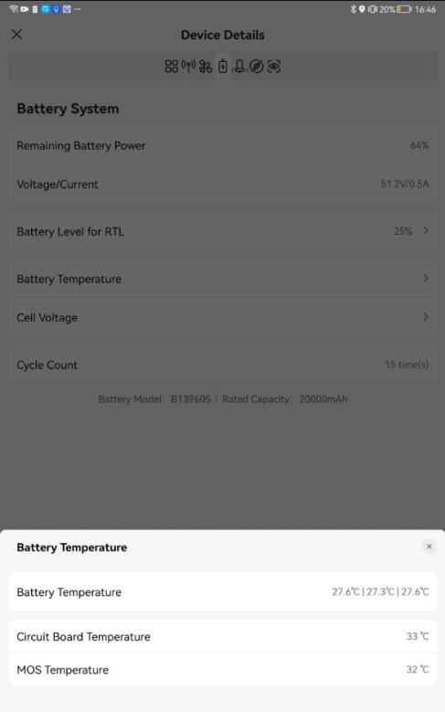
|
Component |
Maximum allowable temperature (Celsius degrees) |
Comments |
|
Battery |
54 |
three temperature sensors built inside the lithium core, real time measurement |
|
Circuit Board |
70 |
real time measurement |
|
MOS |
70 |
real time measurement |
if the UAV reaches maximum allowable temperature of circuit board, MOS or battery temperature,
- the UAV will land immediately during the flight mission
- the UAV will not take off when starting the flight mission.
- the App will prompt warnings
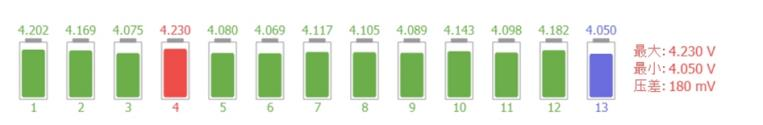
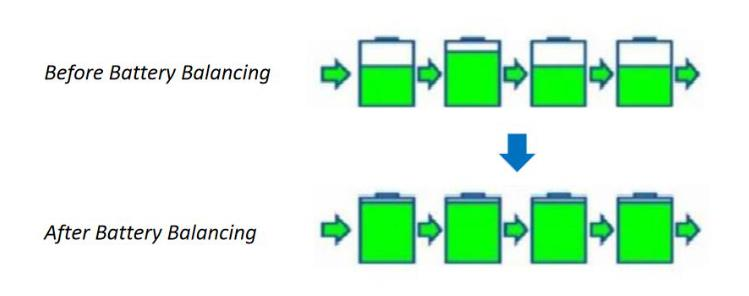
Check the battery balancing. It means that the voltage of each cell of the battery pack should be balanced. Also, the voltage difference of each cell is “voltage gap”, the voltage gap of each cell should not exceed too much. Therefore, we have to ensure that when each cell is being charged and discharged, the voltage rise and fall are within a balanced and acceptable range.
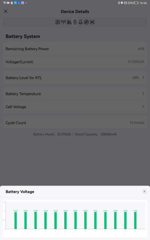
If you find battery balance lost (greater than 150 mV). Please turn off the battery immediately and move this battery to a safe place. Leave the battery alone for a few days and check if the cells can recover. If it can’t, the battery may be scrap. Please contact XAG technician.
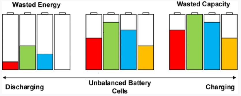
Knowledge of battery balancing.
Imagine that our battery pack is like different reservoirs, the same as the water pressure of each reservoir thus the same output of each reservoir. If we cannot ensure the equal level of water pressure of each reservoir, it will lead to one pool is dry and the other pool is still full. However, their staff will not check the remaining capacity of each reservoir, then a single pool will be overcharged due to refilled water uniformly.
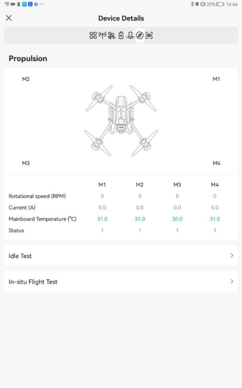
Propulsion System Check
Propulsion Details
This page has the detailed information regarding to the electrical speed controllers (ESCs).
Please check these ESCs before flight mission.
Idle Test (Mandatory)
 During idle test, make sure there are no people nearby within 10 meters.
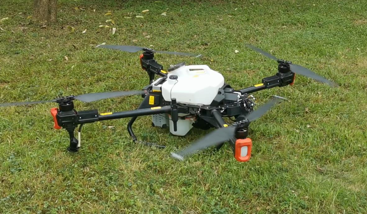
For good practices, idle test should be performed regularly. If the UAV is recently repaired or under maintenance, it’s necessary to perform idle test before flight mission.
Things that need to be checked:
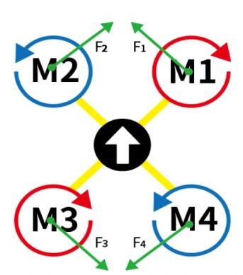
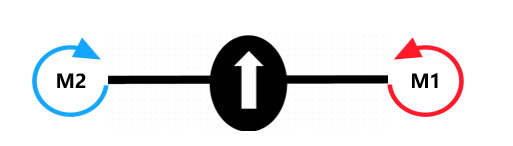
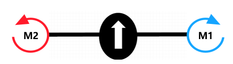
- Propellers rotation direction: Turn on/off the motor individually to identify the propellers rotation direction. Make sure the propellers’ rotation direction is the same as shown in the diagram.
- Rotational speed (RPM); The difference among M1~4 should be less than 50 RPM.
3. Current (A); Check if the current is within range.
|
UAV model |
Average Current (A) |
Max. Current (A) |
|
P40 |
1 |
2.5 |
|
P100, V40 |
2 |
5 |
4. Mainboard Temperature; maximum 90°C
5. While the motors are rotating, listen if the motor sound is normal.


Check the propellers rotation direction
|
UAV Model |
Diagram |
|
P100 EN/CN P40 EN/CN |
|
|
V40 CN |
|
|
V40 EN |
|
if the above items are checked and OK, you can perform a “take off and land” test
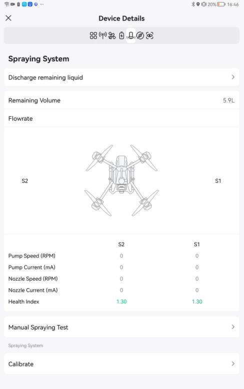
Spraying System Check
Spray System Details
Feel free to try all the items under the spray system details.
|
|
|
|
Item |
Usage |
|
Discharge remaining liquid |
Remove the remaining liquid inside the tank. Clean liquid tubes; |
|
Remaining volume |
Check the remaining volume |
|
Real-time flowrate |
It’s the real-time measurement of speed and current. Check if there are abnormal current and speed, for example, large current, no current, etc. |
|
Manual spray test |
Test the functionality of spray system; It’s suggested to perform spray manual test after repair |
|
Calibrate |
Calibrate spraying system; this is optional. You can perform the spray calibration regularly. It’s suggested to perform spray calibration after repair |
Manual Spraying Test
Pour water into the liquid tank
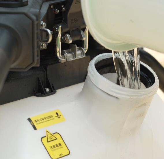
Make sure the remaining volume has enough liquid to perform manual spray test.
You are allowed to set the individual pump flow rate and nozzle speed.
The speed and current measurement of S1 and S2 should be very close.


Please check the followings
- Tubes no leakage
- Normal spray disk spin
- Flow-out liquid without bubbles
 if the liquid viscosity is too high, spray calibration is required.
The below example is that high viscosity chemicals result large droplet.


[velocity 8m/s, 8L/ha, spray width 6.5m, height 3m, droplet size 80rm]
Three possible causes big droplets:
- High velocity
- High flight speed
- High viscosity chemical
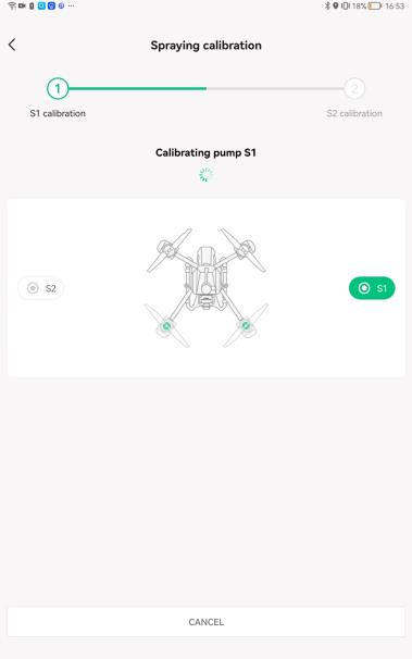
Spraying Calibration (Optional)
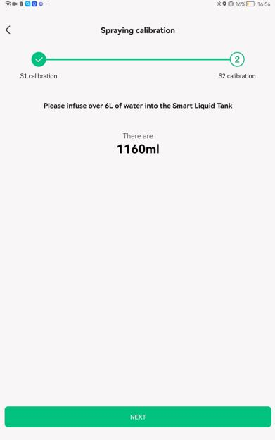
Each nozzle needs at least 6L water to calibrate.
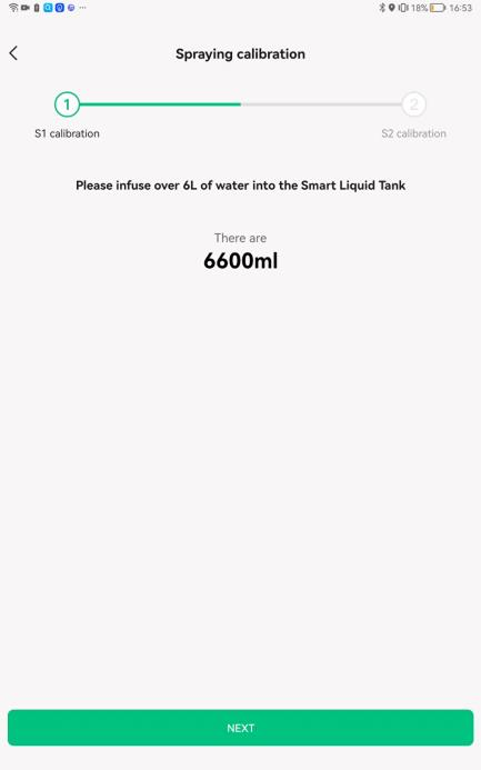
During spray calibration, the pump will deliver 6L water to the nozzle and the water will flow out of the UAV through nozzles. For the models before 2020, users were asked to place a measuring cup under the nozzle to know how much water was pumped by certain rotations of a pump. For the models after 2020, the liquid level sensor will measure and verify the volume of pumped water by itself.


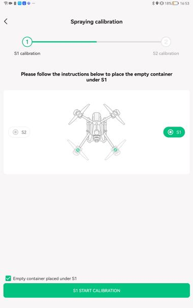
Spraying calibration is in process, it will stop and inform when finished.
S1 spraying calibration is completed. It’s ready to move forward to S2 calibration
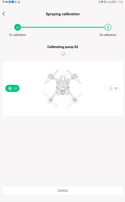
S2 spraying calibration is in process
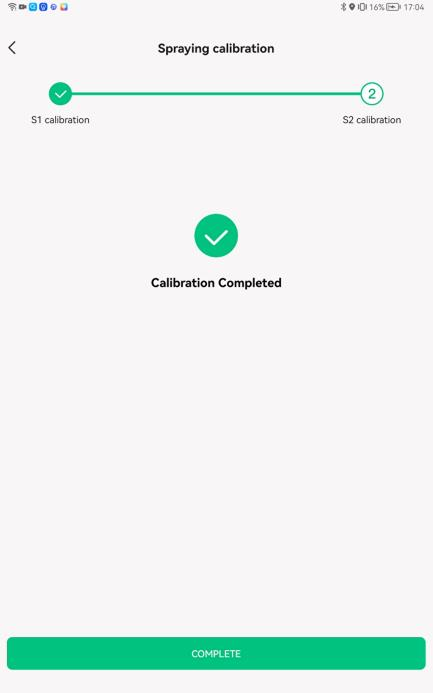
calibration completed
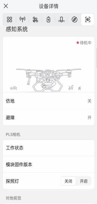
Sensing System Check
Make sure there are no red warning sign. Otherwise, the sensing system is malfunctioned.